
Robohub.org
Building a Tablebot
There was a shortage of entries in the tablebot competition shortly before the registration window closed for RoboGames 2023. To make sure the contest would be held, I entered a robot. Then I had to build one.
What’s a tablebot?
A tablebot lives on the table. There are three “phases” to the competition:
- Phase I: Build a robot that goes from one end of a table to the other and back.
- Phase II: Have the robot push a block off the ledge of the table.
- Phase III: Have the robot push the block into a shoebox mounted at the end of the table.
There is also an unofficial Phase IV – which is to fall off the table and survive. I did not attempt this phase.
The majority of tablebots are quite simple – a couple of sonar or IR sensors and they kind of wander around the tabletop in hopes of completing the different phases. My tablebot is decidedly different – and it paid off as the robot won the gold medal at RoboGames 2023.
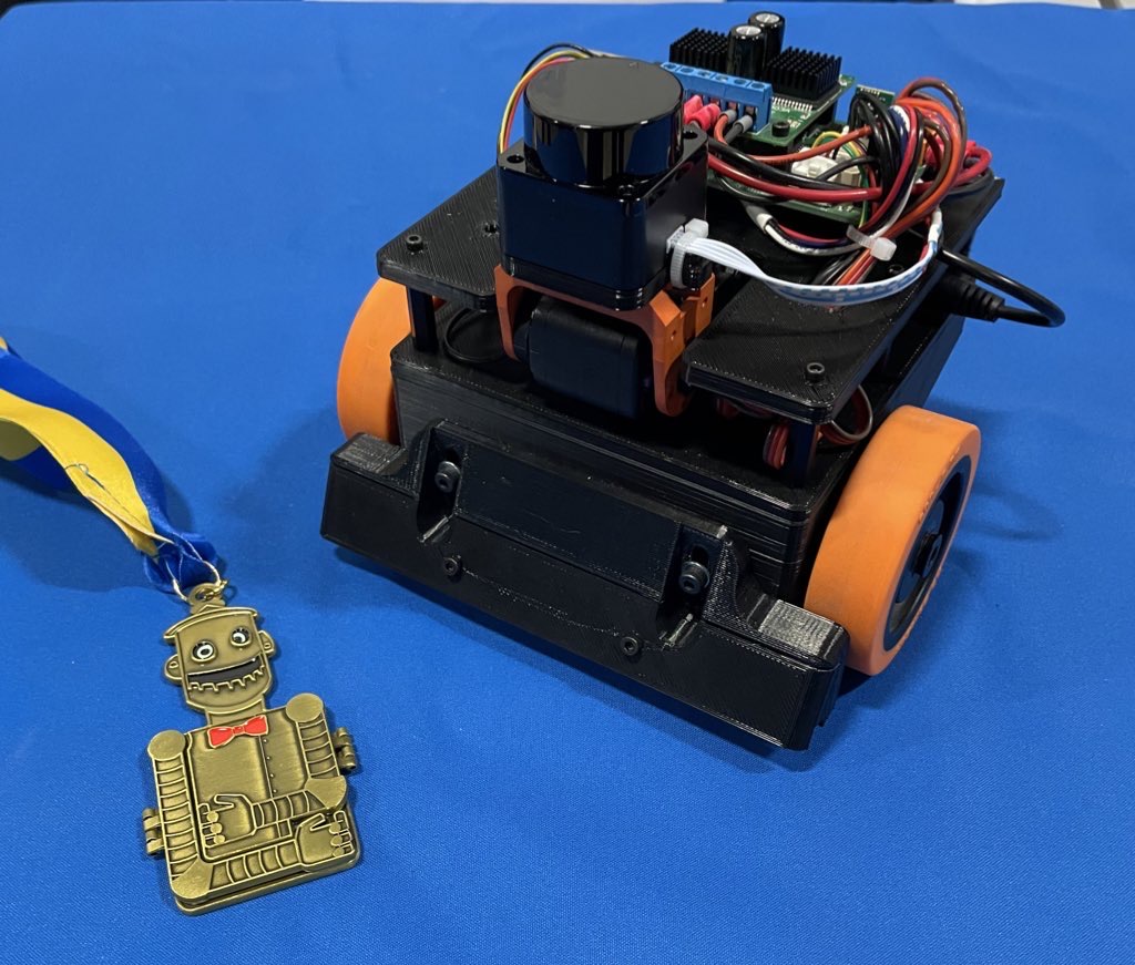
Robot build
The entire robot is built of 3D printed parts and random things I had on hand.
I’ve had one of those $99 LD-06 lidars sitting around for a while, and decided this was a great project to use it on. I used a Dynamixel AX-12 servo to tilt the laser so I can find the table, the cube, or the goal.
All of the code runs on an STM32, on my custom Etherbotix board which was designed for my Maxwell robot a number of years ago. The robot uses differential drive with some 30:1 12V gear motors, which were purchased from Lynxmotion in 2008 and used in various fire fighting robots over the years.
A set of small digital Sharp IR sensors are used as cliff sensors. These can be moved up or down to calibrate for different table surfaces using a pair of adjustment screws. While the sensors are very accurate and stop the robot, they don’t see far enough ahead when going at full speed, and so I also use the laser to detect when the table edge is approaching.
Phase 1 Software
Phase 1 is pretty straight forward – and mostly based on dead reckoning odometry:
- The laser is angled downwards looking for the table. This is done by projecting to the scan to 3D points, and filtering out anything not in front of the robot at roughly table height. When the table disappears (number of points drops too low), we reduce our maximum speed to something that is safe for the cliff sensors to detect.
- While the laser sensors look for the end of the table, the robot drives forward, and a simple feedback loop keeps the robot centered on the table using odometry.
- When the cliff sensors eventually trigger, the robot stops, backs up 15 centimeters, and then turns 180 degrees – all using dead reckoning odometry.
- The maximum speed is then reset and we take off to the other end of the table with the same behavior.
Phase 2 Software
The movements of Phase 2 are basically the same as Phase 1 – we drive forward, staying centered with odometry. The speed is a bit lower than Phase 1 because the laser is also looking for the block:
- The laser scan is projected to 3D, and we filter out any points that are part of the table based on height. These remaining points are then clustered and the clusters are analyzed for size.
- If a cluster is a good candidate for the block, the robot turn towards the block (using, you guessed it, dead reckoning from odometry).
- The robot then drives towards the block using a simple control loop to keep the heading.
- Once the block is arrived at, the robot drives straight until a cliff sensor trips.
- At that point, the robot stops the wheel on the side of the tripped cliff sensor and drives the other wheel very slowly forward so that we align the front of the robot with the edge of the table – ensuring the block has been pushed off the table.
Phase 3 Software
The final phase is the most complex, but not by much. As with the earlier phases, the robot moves down the table finding the block:
- Unlike in Phase 2, the robot actually approaches a pose just behind the block.
- Once that pose has been reached, the robot tilts the laser back to level and finds the goal.
- The robot then turns towards the goal in the same way it first turned towards the block.
- The robot then approaches the goal using the same simple control loop, and in the process ends up pushing the block to the goal.
All of the software for my Tablebot is availble on GitHub.
Robogames video
Jim Dinunzio, a member of the Homebrew Robotics Club, took a video during the actual competition at Robogames so you can actually see the winning set of runs:
Visualization
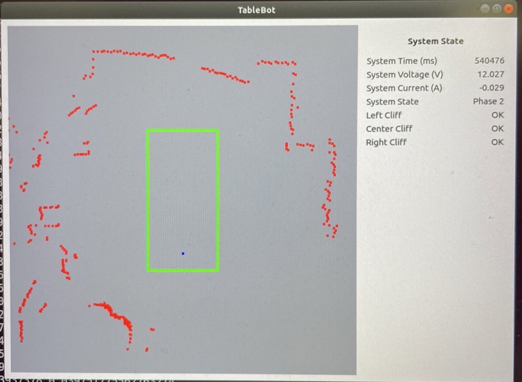
To make development easier, I also wrote a Python GUI that renders the table, the robot odometry trail, the laser data, and detected goals and cubes.
Fun with math
Along the way I actually ran into a bug in the ARM CMSIS DSP library. I used the arm_sin_cos_f32() function to compute my odometry:
arm_sin_cos_f32(system_state.pose_th * 57.2958f, &sin_th, &cos_th);

system_state.pose_x += cos_th * d;

system_state.pose_y += sin_th * d;

system_state.pose_th = angle_wrap(system_state.pose_th + dth);
This function takes the angle (in degrees!) and returns the sine and cosine of the angle using a lookup table and some interesting interpolation. With the visualization of the robot path, I noticed the robot odometry would occasionally jump to the side and backwards – which made no sense.
Further investigation showed that for very small negative angles, arm_sin_cos_f32 returned huge values. I dug deeper into the code and found that there are several different versions out there:
- The version from my older STM32 library, had this particular issue at very small negative numbers. The same bug was still present in the official CMSIS-DSP on the arm account.
- The version in the current STM32 library had a fix for this spot – but that fix then broke the function for an entire quadrant!
The issue turned out to be quite simple:
- The code uses a 512 element lookup table.
- For a given angle, it has to interpolate between the previous and next entry in the table.
- If your angle fell between the 511th entry and the next (which would be the 0th entry due to wrap around) then you used a random value in the next memory slot to interpolate between (and to compute the interpolation). At one point, this resulted in sin(-1/512) returning outrageous values of like 30.
With that bug fixed, odometry worked flawlessly afterwards. As it turned out, I had this same function/bug existing in some brushless motor control code at work.
Robogames wrap up
It is awesome that RoboGames is back! This little robot won’t be making another appearance, but I am starting to work on a RoboMagellan robot for next year.

AUAI is supported by: