
Robohub.org
Hands on ground robot & drone design series part I: mechanical & wheels
This is a new series looking at the detailed design of various robots. To start with we will be looking at the design of two different robots that were used for the DARPA Subterranean Challenge. Both of these robots were designed for operating in complex subterranean environments, including Caves, Mines & Urban environments. Both of these robots presented are from the Carnegie Mellon University Explorer team. While I am writing these posts, this was a team effort that required many people to be successful. (If anyone on Team Explorer is reading this, thank you for everything, you are all awesome.)
These posts are skipping the system requirements step of the design process. See here for more details on defining system requirements.
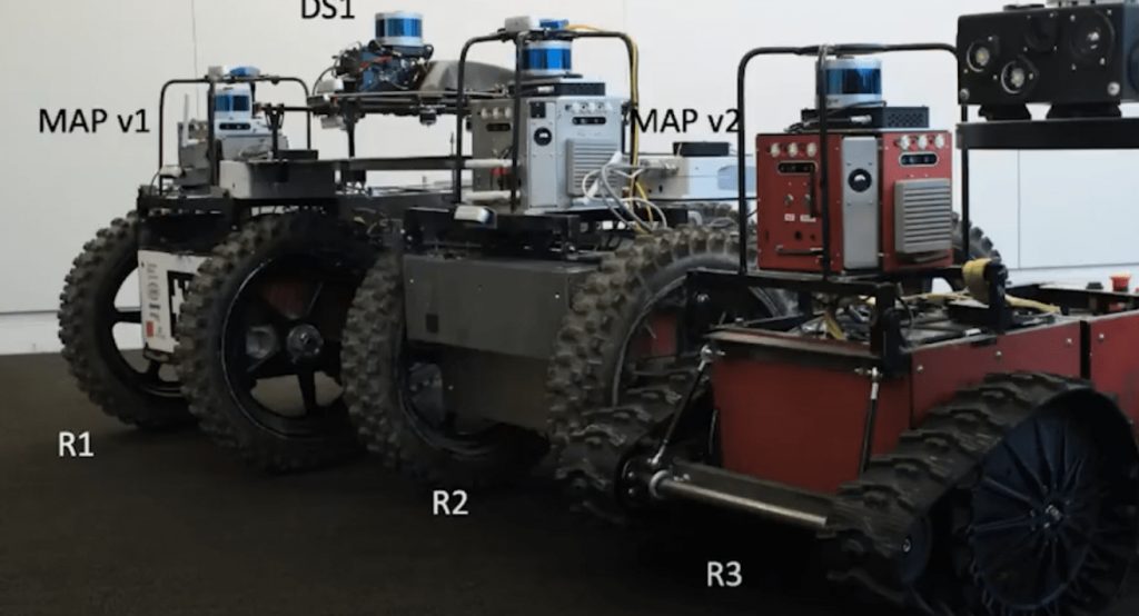
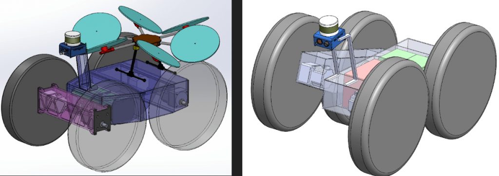
SubT Ground UGV and DS Drone ImageTeam Explorer R1 Ground Robot and DS Drone [Source]
R3 Ground robot (UGV)
For the SubT challenge three ground vehicles were developed all of a similiar design. The ground robots were known with the moniker of R#, where # is the order we built them in. The primary difference between the three versions are
R1 – Static Chassis, so the chassis has minimal ground compliance when driving over obstacles and uneven surfaces. R1 was initially supposed to have a differencing mechanism for compliance, however due to time constraints it was left out from this first version. R1 is pictured above.
R2 – Has the differencing mechanism and was designed as initially planned.
R3 – Is almost identical to R2, but smaller. This robot was built for navigating smaller areas and also to be able to climb up and down steps. It also uses different motors for the driving the wheels.
DS drone
The original drone design used by Team Explorer called their drones D1, D2, etc.. This let a combination of UGV +Drone go by joint designations such as R2D2. Early on, the team switched to a smaller drone design that was referred to as DS1, DS2, etc.. Where DS is short for Drone Small.
The drone design post are split into two sections. The first is about the actual drone platform, and the second is about the payload that sat on top of the drone.
Mechanical & wheels
Robot size decision
After we have the list of system requirements we start with the design of the mechanical structure of the robot. In this case we decided that a wheeled robot would be best. We wanted to have the largest wheels possible to help climb over obstacles, however, we also needed to keep our sensors at the top of the vehicle above the wheels and be able to fit in openings 1 x 1 meters. These requirements set the maximum size of the robot as well as the maximum size of the wheels.
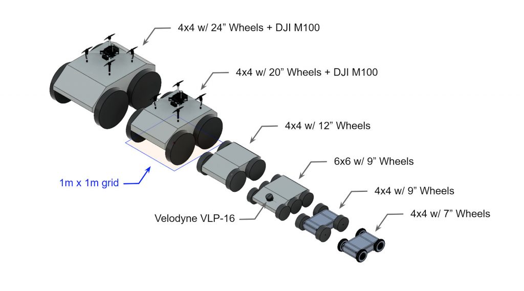
The final dimensions of the first two vehicles (R1 and R2) were around (L x W x H) 1.2 x 0.8 x 0.8 meters (3.9 x 2.6 x 2.6 ft). The third smaller vehicle was around 1 x 0.6 m (3.2 x 1.9 ft) and designed to fit through 0.7×0.7 m openings.
Steering approach
Early on we also needed to determine the method of driving. Do we want wheels or tracks? Do we want to steer with ackerman steering, rocker-bogie, skid steer, etc.?
See here for more details on steering selection.
We chose to use a skid steer four wheeled drive approach for the simplicity of control and the ability to turn in place (point turns). At the start of the competition we were not focused on stair climbing, which might have changed some of our design decisions.
Suspension
The next step was to determine the suspension type. A suspension is needed so that all four of the wheels make contact with the ground. If the robot had a static fixed frame only three of the wheels might make contact with the ground when on uneven surfaces. This would reduce our stability and traction.
We decided early on that we wanted a passive suspension for the simplicity of not having active components. With a passive suspension we were looking at different type of body averaging. We roughly had two choices, front-pivot or side-to-side.
Left image shows a front-pivot approach. Right image shows a side-to-side differencing method.
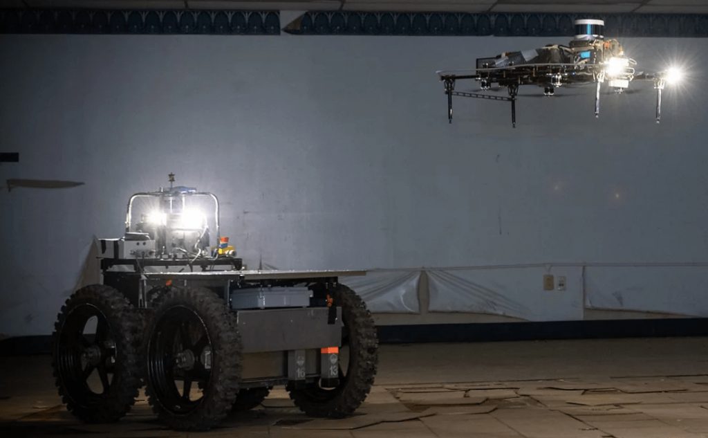
We decided to choose the front-pivot method, however we decided to make the pivot be roughly centered in the vehicle. This allowed us to put all of the electronics in the front and the batteries in the rear. The front-pivot method we felt would be better for climbing up stairs and for climbing over obstacles on level’ish terrain. Also importantly this approach made it easier to carry a drone on the ground vehicle.
Chassis design
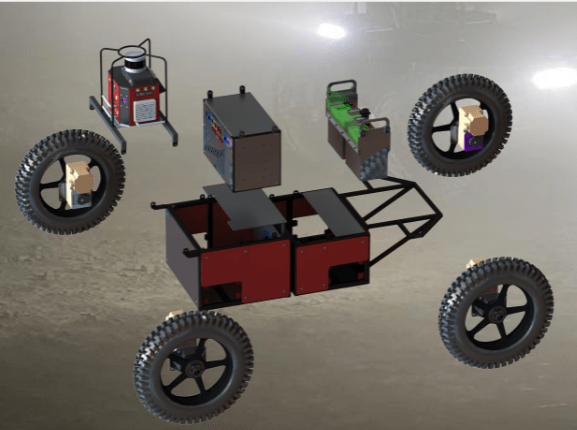
At this point we started designing the chassis. This was an important step so that we could estimate the total weight in order to spec the drive-train. Ideas for the chassis were everything from building with 80/20 to building an aluminum frame and populating it with components, to a solid welded chassis. We selected to use a welded steel tube chassis for the strength. We needed a robot that could survive anything we did to it. This proved to be a wise decision when the robot crashed or fell over cliffs. The downside of the steel was increased mass.
For the pivot we found a large crossed roller bearing that we were able to use to attach the two steel boxes together. The large bore in the middle was useful for passing wires/cables through for batteries, motors, etc…
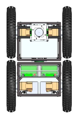
Part of the chassis design was also determining where all of the components should mount. Having the batteries (green boxes in image above) in the rear helps us climb obstacles. Other goals were to keep the ground clearance as high as possible while keeping the center of gravity (CG) as low as possible. Since those are competing goals, part of the design process was to develop a happy medium.
In order to maintain modularity for service, each wheel module had the motor controller, motor, gear box, and bearing block as a solid unit that could be swapped between robots if there was any issues. This also allowed most of the wiring to be part of that block. The only cables that needed to be connected to each of the modules from the robot were power, CAN communications, and the emergency stop line; all of which were connectorized.
For electronics on R1 and R2 we built an electronics box that was separate from the robot and could be removed from the robot as needed. On R3 we built the electronics into the robot itself. This modular approach was very useful when we had to do some welding to the chassis post-build for modifications. The downside of the modular approach for electronics was that working in the electronics box was more difficult then in the open R3. Also the time for fabricating and wiring the R1/R2 electronics boxes was considerably more than the open R3 electronics. We also had several failures during testing related to the connectors from the electronics boxes.
Wheel design
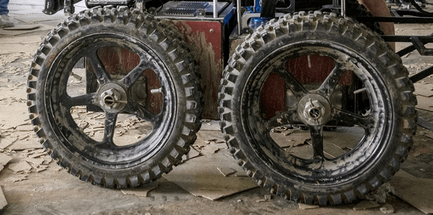
We debated a lot about what type of wheel to use, ultimately we used motorcycle wheels due to the simplicity of obtaining them and mounting them. The wheel diameter we desired also lined up very well with motorcycle wheels. In order to get better traction and ability to climb over obstacles we liked the wider tires.
R1 and R2 had a wheel diameter of 0.55m, R3 had a wheel diameter of 0.38m. This gave R1 and R2 a ground clearance of 0.2m, and R3 a ground clearance of 0.12m.
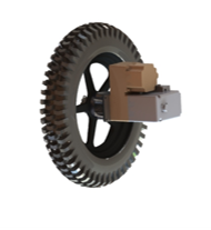
The wheel hubs ended up being a different story. We found solid metal rims that we had to machine large amounts of metal out of in order to balance the strength and the weight.
The R1 and R2 robots were around 180kg (400lb)*, the wheels were for a vehicle significantly heavier. As such we put a small amount of pressure in the wheels to keep them from falling off, however we tried to keep the pressure low to increase the ground compliance of the wheels. This method added a very small amount of compliance, we tried removing some of the rubber from the sidewalls, but was not able to get a happy medium between limiting the wheel deforming during point turns and increasing ground compliance.
We were also concerned how the motorcycle tires would do when point turning and if we would rip the wheels from the rims. To counter this we installed a beadlock system into each of the wheels. The beadlock was a curved segment installed in multiple places to sandwich the tire to the rim. We never had a wheel separate from the rim, so our approach definitely worked, however it was a pain to install.
*R3 was around 90 kg (200 lbs). We tried using different wheels and tracks to get R3 to climb stairs well. However that story is for another post…
The black rims were solid metal that we machined the wedges into in order to lightweight them. The 3 metal posts in those wedges are the beadlock tensioning bolts. You can also see the castle nut and pin that holds the wheel to the axle. This image is from R2, you can see the gap between the front and rear sections of the robot where the pivot is.
Drive-train selection
Now that we had a mass estimate and system requirements for speed and obstacle clearance we can start to spec the drive-train. The other piece of information that we needed and had to discuss with the electrical team was the voltage of the battery. Different bus voltages greatly affects the motors available for a given speed and torque. We decided on a 51.2v nominal bus voltage. This presented a problem since it was very hard to find the speed/torques we wanted at that voltage. We ended up selecting a 400W 1/2HP motor+gearbox from Oriental Motors with a parallel 100:1 gearbox that allows us to drive at a maximum speed of 2.5m/s.
The part numbers of the motors and gearbox on R1 and R2 were BLVM640N-GFS + GFS6G100FR.
The part numbers of the motors and gearbox on the smaller R3 were Maxon EC 90 Flat + GP81A.
Next steps
Now that we know the mechanics of the robot we can start building it. In the next post we will start looking at the electronics and motor controls. While the nature of the blog makes it seem that this design is a serial process, in reality lots of things are happening in parallel. While the mechanical team is designing the chassis, the electrical team is finding the electrical components needed in order for the mechanical person to know what needs mounted.
It is also important to work with the electrical team to figure out wire routing while the chassis is being developed.
Note of the editor: This post has been merged from the posts “Hands On Ground Robot & Drone Design Series” and “Mechanical & Wheels – Hands On Ground Robot Design“.