
Robohub.org
Arduino for Makers #1: Setting up a development station
In this new tutorial series, robotics educator and author Myke Predko will introduce you to the basics of Arduino with simple projects that can be created in just a few minutes with inexpensive and easy-to-obtain parts. Along the way, you will learn how to get the most out of electronics, how to create software that is easy to understand and debug, and you will develop the toolset you need to determine whether or not the Arduino is the right choice for your own project, and if so, how to implement it efficiently. The series is for anyone interested in Arduino, from high school students to professional engineers. As a follow up to his introduction to the series, in this tutorial Myke gives directions for setting up your own Arduino development station. Look for new lessons every 2-3 weeks.
Most “getting started” Arduino tutorials start by getting to you build a flashing LED application. While the application I present here is similar, rather than just getting the Arduino’s built-in LED to flash as a “one off” application, we will be setting up the parts and tools for projects that we will implement in the future. While I provide you with the tools to create your first Arduino application, you’ll be preparing for creating your own Arduino-based robots down the line.
Before we get started, let’s talk about some basic electrical rules you will need to understand for this project. Chances are you already know them, but it never hurts to spend a minute and review:
- Current flows from positive voltage (marked with red) to negative voltage (marked with black, and often referred to as “ground” or “Gnd”).
- Current flows through an LED in only one direction (which causes it to light) and the negative connection is normally marked with a flat on its package.
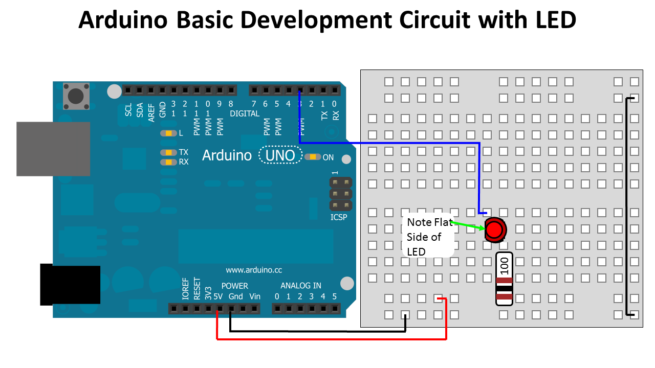
As I go on with the article series, I will expand upon these electrical rules, but this is all you have to know for now. If you look at Figure 1 at the start of this article, you will see that positive voltage from the Arduino has a red connection, the negative (Gnd) has a black connection, and the LED has a flat side that indicates for the direction of current flow through the device.
The parts needed for this first iteration of your Arduino development station are:
- Arduino Uno (R3 or R3 SMD). When you start out, I recommend that you use the “R3” version with the long rectangular chip in a socket rather than the small, flat square chip. The socketed chip can be replaced if it is ever damaged and it is about $5.00 cheaper.
- Breadboard for quickly creating (and taking apart) your circuits.
- 5mm PTH red LED. This common LED consists of a red “bead” that lights when current passes through it. As noted above, current only flows through an LED in one direction with the negative connection marked with a flat on the side of the package.
- 100 Ohm, 1/4Watt resistor. This part reduces the current that will flow through the LED. While you can get a single 100 Ohm resistor, I recommend that you get a kit of resistors so that you have a stock of different values that can be applied in different circumstances.
- 22 gauge wire. This is for connections – it is worth purchasing a breadboard wiring kit with precut and stripped wires for the breadboard.
There are many places where these parts can be bought. At the end of the article, I have provided pointers to Sparkfun and their part numbers for the components listed above. Sparkfun is an excellent supplier and one that I feel confident recommending – but I should point out that you may want to explore local electronics shops in your area. None of the components are hard to get and chances are you can buy the components locally for about the same price without having to wait for shipping.
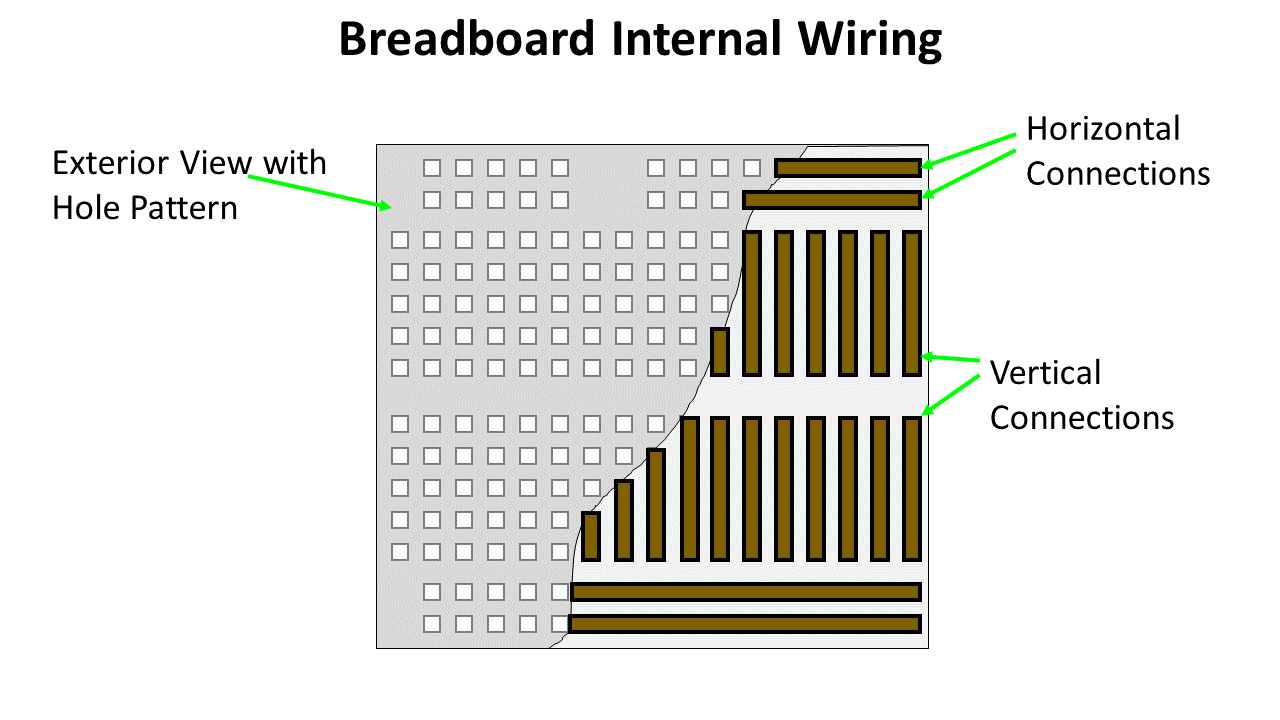
The “Breadboard” is a type of electronic circuit board in which wires and component leads can be pushed into (and pulled out of) to make simple circuits quickly. As can be seen in Figure 2, the middle holes are connected together vertically while the holes on the outside rows are connected horizontally. I place components in the central area and let the vertical connections connect components together while the horizontal connections are used for “power rails”. Note that I connect the ground power rails on both sides of the breadboard, but only provide power to one side; I will be discussing the reason for this in a future article.
The “5V” and “Gnd” connections from the Arduino to the Breadboard power rails are a convention that I will be using for future articles. This setup allows for fast wiring of application circuitry while allowing for high power devices to be supplied separately and not from the Arduino. Many Arduino applications use its power supply in ways that could lead to burning it out or worse. This wiring convention and reasons behind it will be discussed in future articles.
With the electronics parts together, there are a few tools that I recommend that you buy at this time:
- Plastic kit box to provide for quick clean up and transportation to other locations. This should have separate compartment for various parts and tools. I like the Stanley Sortmaster because the compartment separators can be set to allow storage of larger parts, and there is very little chance that the small parts in one compartment will find their way into another.
- 6’ A-B USB Cable.
- Needle nose pliers.
- Wire strippers. These can double as wire cutters.
All these components can be purchased at a local dollar store. The USB Cable really doesn’t belong as a “tool”, but I wanted to make the point of looking for it at a dollar store – it will be considerably cheaper at a dollar store than at a specialty electronics store.
With the parts and tools available, you can now wire the circuit as shown in Figure 1. The circuit is quite simple: an LED with 100 Ohm resistor is connected to the “5V” output of the Arduino and the Arduino’s pin “3”. When pin “3” outputs a “LOW” voltage, current flows through the LED and it lights. When pin “3” outputs a “HIGH” voltage, current no longer flows through the LED and it no longer lights. This action can be tested by connecting the Arduino to your PC using the USB power (which provides power to the circuit) followed by disconnecting the wire from the Arduino’s pin 3 (the LED’s negative (flat) side) and connecting it to the 5V rail or one of the two Gnd rails on the breadboard.
As a side point, I highly recommend designing your circuits so they can be tested easily without requiring any Arduino software. I guarantee you that it will save hours of wondering why Arduino code doesn’t seem to be working when the real problem is that there is something wrong with the electrical circuit.
With the application built, you’re now ready to create the Arduino code to test everything out. At the end of the article, I have provided the download page for the Arduino software development environment (often called “Arduino Software”) (referred to here as the “Arduino Sketchpad”) and there are specific instructions for installing the software. It can be loaded into Windows PCs, Macs or Linux systems, and just takes a few minutes to install.
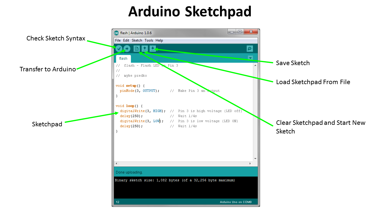
The Arduino Sketchpad’s many options can be somewhat overwhelming to new users, and for that reason, I suggest that beginners focus on the five icons that are labeled in Figure 3; these are the only controls that will be required for quite a while.
When you have your Arduino Sketchpad up and running, cut and paste in the following program:
// flash - Flash LED on Pin 3
//
// myke predko


void setup() {
 pinMode(3, OUTPUT); // Make Pin 3 an Output
}


void loop() {
 digitalWrite(3, HIGH); // Pin 3 is high voltage (LED off)
 delay(250); // Wait 1/4s
 digitalWrite(3, LOW); // Pin 3 is low voltage (LED ON)
 delay(250); // Wait 1/4s
}
Then, click the “Save Sketch” icon to save the Sketch (which is what the Arduino application is called), and then click on the “Transfer to Arduino” (aka “Upload”). After a few seconds, you will get the “Done uploading” message and the LED should start flashing (if it doesn’t then use the hint above for debugging the application – chances are you have the LED orientated the wrong way or the resistor connected to the wrong power rail).
Now, you have a working Arduino development station. I know it doesn’t seem like much right now, but in the coming weeks, we’ll look at using this as a base for learning more about Arduino and creating your own robots.
Further Reading:
- http://arduino.cc/en/main/software Arduino Software Download Page
- http://forum.arduino.cc/index.php?board=2.0 Arduino “Installation & Troubleshoot” Forum
- http://www.ladyada.net/learn/arduino/lesson1.html First project tutorial
- http://electronicsclub.info/leds.htm Introduction to Light Emitting Diodes (LEDs)
- http://www.electronics-tutorials.ws/resistor/res_9.html Resistor Tutorial and Summary
Parts:
- https://www.sparkfun.com/ for parts:
- https://www.sparkfun.com/products/11021 Arduino Uno – R3
- https://www.sparkfun.com/products/9590 LED – Basic Red 5mm
- https://www.sparkfun.com/products/10969 1/4W Resistor Kit
- https://www.sparkfun.com/products/9567 Breadboard – Translucent
- https://www.sparkfun.com/products/124 Jumper Wire Kit
Previous Article: Arduino for Makers #0: Introduction to the series
Next Article: Arduino Programing deconstructed
tags: Arduino for Makers, Arduino tutorial, c-Education-DIY, tutorial