
Robohub.org
Make your own Dtto Modular Robot – Assembly instructions (Part 1 of 3)
Source: Alberto Molina
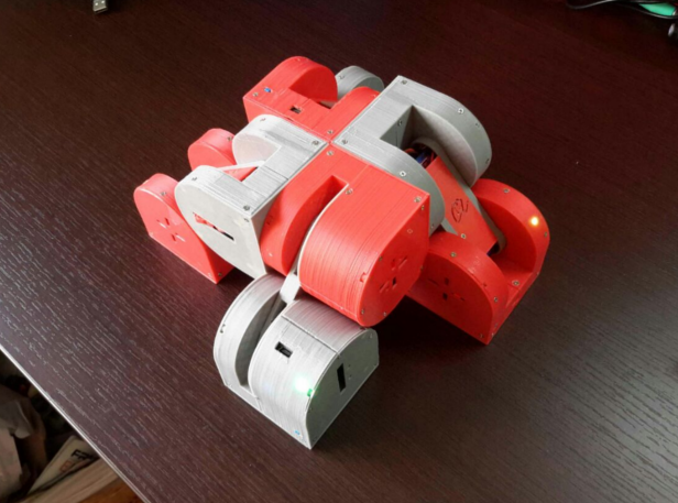
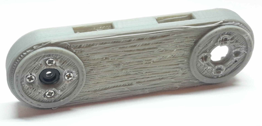
This tutorial shows how to assemble a fully working Dtto Modular Robot module.
This robot is inspired by the MTRAN III, by the National Institute of Advanced Industrial Science and Technology (AIST), Japan.
We strongly recommend you have a rasp (also called: nail file, emery board, or sandpaper) close by and a set of precision blades.
First of all, we need to print all the robot parts. For this type of project, we think that ABS plastic is better as it is more machinable than others. All .stl files are available in the links below. You also have a link to a PDF file detailing how many parts we need, part numbers and some details (list of 3D printed parts). We will be using the part number to identify the parts. We also need the schematics file to check the connections.
Once we have all our parts printed, all supports removed and carefully sanded, we can proceed to the assembly of the module.
It has been fully printed with open-source 3D printers, uses open-source hardware, and has been designed entirely on FreeCad.
Note: In this tutorial, we won’t be assembling the IR detection system. This feature will be available as soon as possible.
We do not take any responsibility and we are not liable for anything occurring while assembling and playing with this modular robot.
All images copyright Alberto Molina.
Source: Alberto Molina
Step 1
This document is an illustrated guide on how to assemble a module (v2) for the Dtto Modular Robot: https://hackaday.io/project/9976-dtto-v20-modular-robot
In the project files, you will find the following documents:
- Bill of materials
- List of 3D printed parts
- Schematics
- STL files for printing
You will find all the documents also on:
https://github.com/otrebla333/Dtto-Modular-Robot
Components:
| Quantity | Description |
|---|---|
| 22 | 3D printed parts |
| 1 | Arduino Nano v3.0 |
| 1 | HC-05 Bluetooth Module |
| 1 | NRF24L01 + Wireless Transceiver |
| 24 | Neodimium Disk Magnets (4x3mm) |
| 2 | TowerPro MG92B Servomotor |
| 3 | TowerPro SG90 Servomotor |
| 2 | Li-Po Battery 3,7V 600mAh 25C |
| 1 | LM317 Voltage Regulator |
| 1 | Mini Switch |
| 1 | WS2812 RGB LED |
| 40 | M1.7x4mm Self Tapper Screw |
| 1 | 330 Ohms Resistor |
| 1 | 1200 Ohms Resistor |
| 4 | 520 Ohms Resistor |
| 3 | Small Rubber Bands (dental braces) |
Step 2
We need:
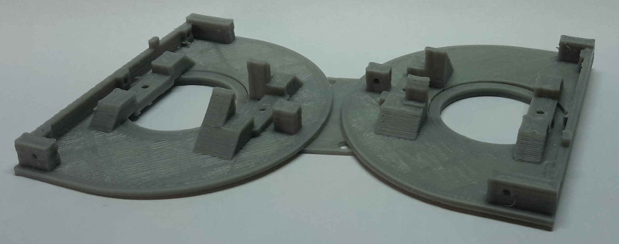
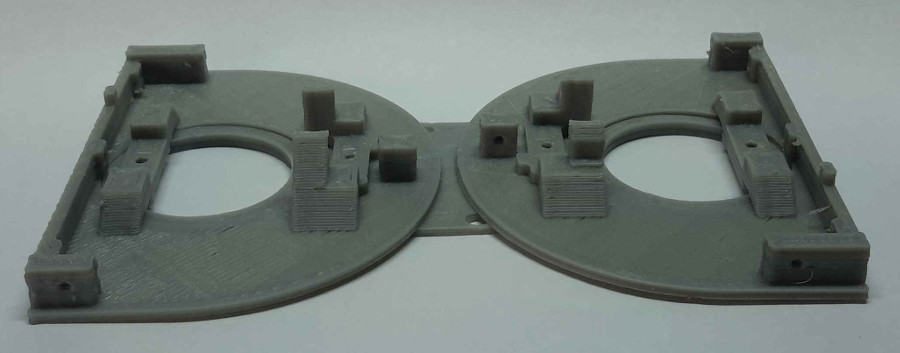
- 2 x Part 004-1
- 1 x Part 011-1
First, we have to ensure these 3 parts fit perfectly. It is very important that the 004-1 parts rotate freely around the center. The easier they rotate the less energy is lost in friction, and the robot moves around better.
Source: Alberto Molina
Source: Alberto Molina
Step 3
We need:
- 2 x MG92B Servomotors
- 4 x 520 Ohms Resistors
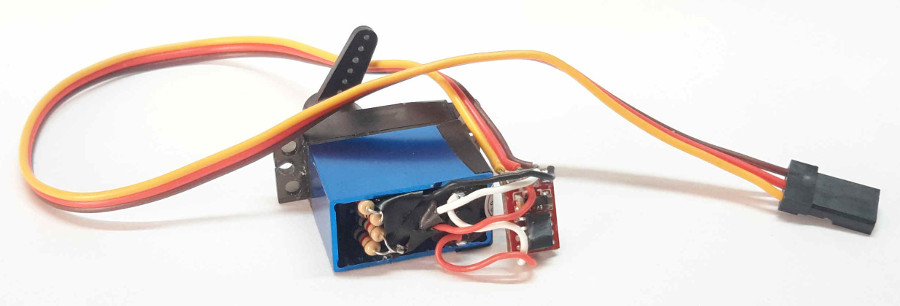
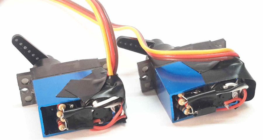
The second thing to do is to adapt the MG92B servomotors to turn the full 180 degrees.
The method we used was to add a couple resistors to each servo control circuit:
- Take apart the back cover of the servomotor (4 screws).
- Carefully separate the control circuit from the inside. The potentiometer is located under the circuit (it may be covered by a black film). Once you can access the 3 pins of the potentiometer, you have to unsolder the first and the third cable (not the center one). Then, you have to solder a 520 ohms resistor to each of these two pins, and then solder the cable to the resistor. You can find tutorials on how to modify servomotors (search: modify servo 180 degree), but it’s important you use the 520 ohms resistors (in the pictures we used one 680 and one 2200 ohms resistor in parallel to get the 520 ohms).
- The control circuit does not fit the casing anymore, so we are going to stick it to the side of the metal case (see pictures). Protect the circuit from short-circuits with some tape on both sides.
- Repeat the procedure for the other servomotor.

Source: Alberto Molina
Source: Alberto Molina
Source: Alberto Molina
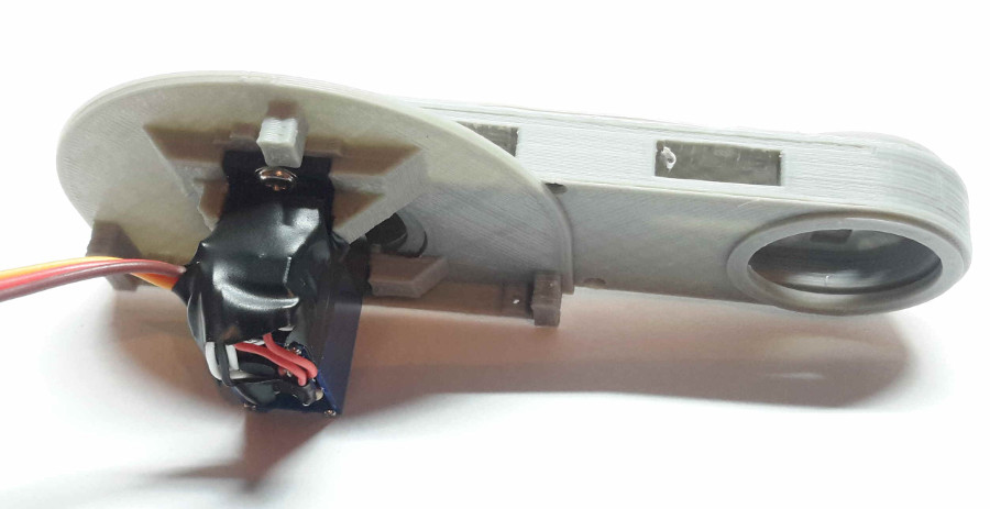
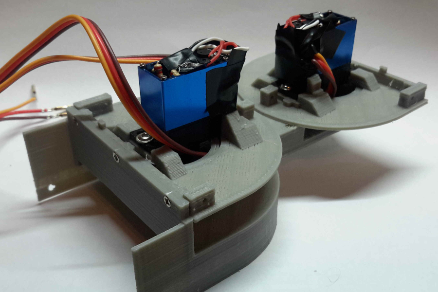
Step 4
We need:
- 2 x Part 004-1
- 2 x MG92B Servomotors (step 3)
In this step, we are going to fix the motors to the printed parts. The motor should fit correctly. We can use the screws that come with the motor, but we will have to cut them to the right length.

Source: Alberto Molina
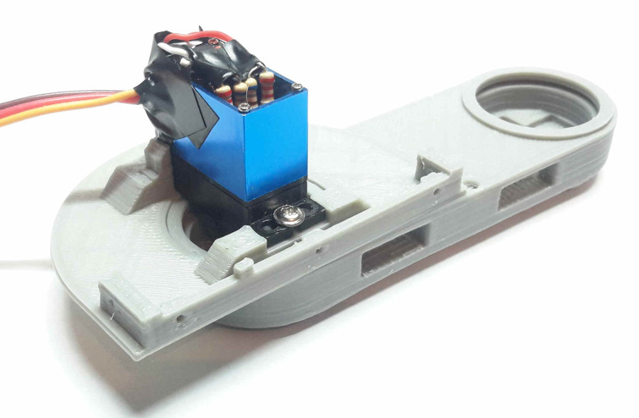
Step 5
We need:
- 1 x Part 011-1
- 1 x Part 012-1
- 2 x Servo Arms (Cross)
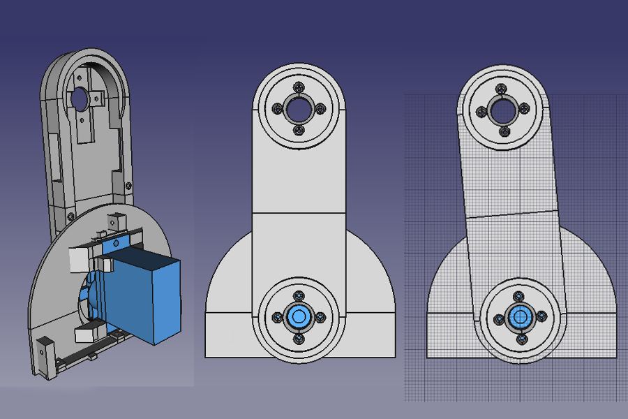
Now we are going to fix the servo arms to the 3D printed part. This step is very important because we have to ensure that the servomotor is centered. If it is not centered, once assembled, the module motor won’t be able to rotate all the way.
The next image illustrates the result. When the servo is set to 90 degrees (servo.write(90)), the relative position of the parts should be like in the center picture. If the position is slightly deviated, like in the picture on the right, we will have to center the part.
Source: Alberto Molina
If we set the servo to 90 degrees and get a deviated position like in the picture on the right, we will have to un-center the servo arm, like in the following picture:
Source: Alberto Molina
Source: Alberto Molina
This is a critical part, so be sure to get a well-centered configuration. Once we get a well-centered part, we have to be completely sure that we have a correct configuration. We can connect the two parts and test the rotation with the “sweep” example in arduino IDE.
Source: Alberto Molina
Source: Alberto Molina
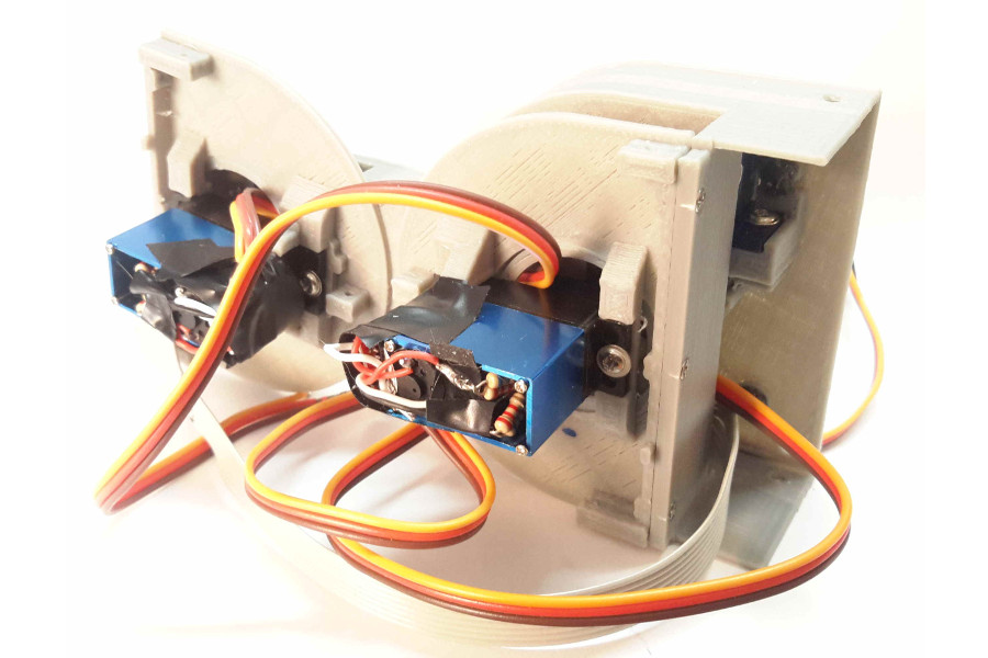
Once we finish with one servomotor, we can proceed to fix the other one.

Source: Alberto Molina

Source: Alberto Molina
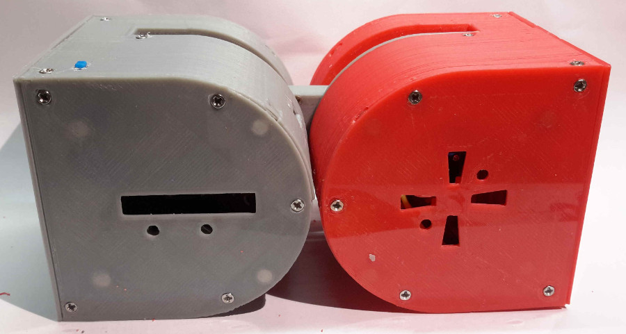
At this moment, the module does not have a male or female part assigned. We will choose one half and we will name it male. The other will be the female half. Then, we have to put the cables of the female motor through the hole in the central part, to the male part. You have to ensure that the cables allow a free rotation of the parts.
Source: Alberto Molina
Step 6
We need:
- 1 x Part 003-1
Now we will start to assemble the male half of the module. First of all we have to ensure that the hole in the part 003-1 fits with the previously assembled part 012-1. Once sanded, we can attach the part 003-1 to the part 004-1 using 3 screws.
Source: Alberto Molina
Tomorrow will feature Part 2, putting magnets on the parts and servos!
This project and all of its files, images and texts are entirely licensed under the CC BY-SA 4.0 license. (http://creativecommons.org/licenses/by-sa/4.0/legalcode).
tags: Alberto Molina, c-Education-DIY, DIY robotics

AUAI is supported by: