Robohub.org
Using hydraulics for robots: Introduction

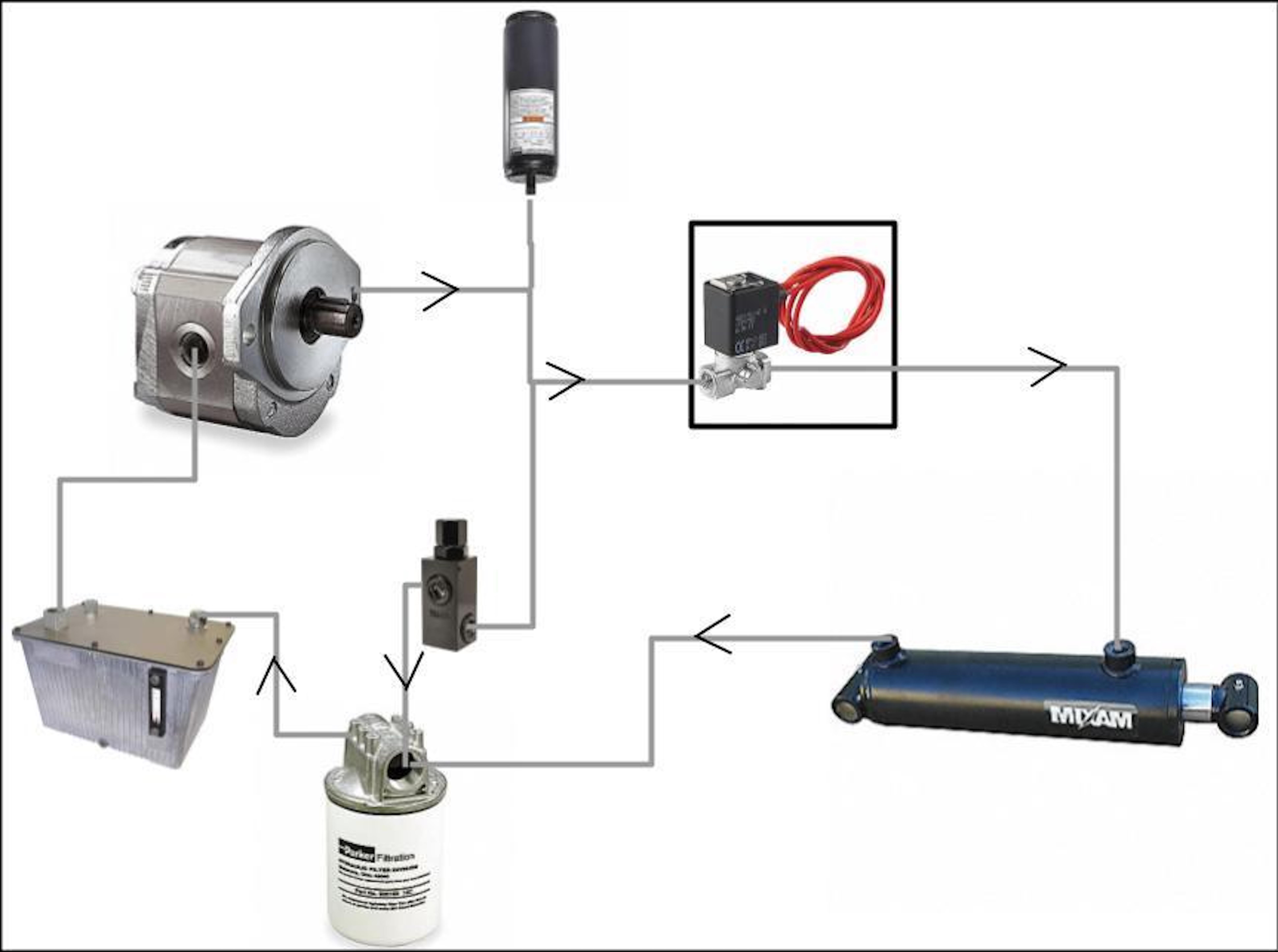
From the Reservoir the fluid goes to the Pump where there are three connections. 1. Accumulator(top) 2. Relief Valve(bottom) & 3. Control Valve. The Control Valve goes to the Cylinder which returns to a filter and then back to the Reservoir.
Hydraulics are sometimes looked at as an alternative to electric motors.
Some of the primary reasons for this include:
- Linear motion
- Very high torque applications
- Small package for a given torque
- Large number of motors that can share the reservoir/pump can increase volume efficiency
- You can add dampening for shock absorption
However there are also some downsides to using hydraulics including:
- More parts are required (however they can be separated from the robot in some applications)
- Less precise control (unless you use a proportional valve)
- Hydraulic fluid (mess, leaks, mess, and more mess)
Hydraulic systems use an incompressible liquid (as opposed to pneumatics that use a compressible gas) to transfer force from one place to another. Since the hydraulic system will be a closed system (ignore relief valves for now) when you apply a force to one end of the system that force is transferred to another part of that system. By manipulating the volume of fluid in different parts of the system you can change the forces in different parts of the system (Remember Pascal’s Law from high school??).
So here are some of the basic components used (or needed) to develop a hydraulic system.
Pump
The pump is the heart of your hydraulic system. The pump controls the flow and pressure of the hydraulic fluid in your system that is used for moving the actuators.
The size and speed of the pump determines the flow rate and the load at the actuator determines the pressure. For those familiar with electric motors the pressure in the system is like the voltage, and the flow rate is like the electrical current.
Pump Motor
We know what the pump is, but you need a way to “power” the pump so that it can pump the hydraulic fluid. Generally the way you power the pump is by connecting it to an electric motor or gas/diesel engine.
Hydraulic Fluid
Continuing the analogy where the pump is the heart, the hydraulic fluid is the blood of the system. The fluid is what is used to transfer the pressure from the pump to the motor.
Hydraulic Hoses (and fittings to connect things)
These are the arteries and veins of the system that allows for the transfer of hydraulic fluid.
Hydraulic Actuators – Motor/Cylinder


The actuator is generally the reason we are designing this hydraulic system. The motor is essentially the same as the pump; however instead of going from a mechanical input to generating the pressure, the motor converts the pressure into mechanical motion.
Actuators can come in the form of linear motion (referred to as a hydraulic cylinder) or rotary motion motors.
For cylinders, you generally apply a force and the cylinder end extends, and then if you release the force and the cylinder gets pushed back in (think of a car lift). This is the classic and most common use of hydraulics.
For rotary motors there are generally 3 connections on the motor.
- A – Hydraulic fluid input/output line
- B – Hydraulic fluid input/output line
- Drain – Hydraulic fluid output line (generally only on motors, not cylinders)
Depending on the motor you can either only use A as the fluid input and B as the fluid output and the motor only spins in one direction. Or some motors can spin in either direction based on if A or B is used as the input or output of the hydraulic fluid.
The drain line is used so when the system is turned off, the fluid has a way to get out of the motor (to deal with internal leakage and to not blow out seals). In some motors the drain line is connected to one of the A or B lines. Also their are sometimes multiple drain lines so that you can route the hydraulic hoses from different locations.
Note: While the pump and motor are basically the same component. You usually can not switch their role due to how they are designed to handle pressure and the pumps usually not being backdrivable.
There are some actuators that are designed to be leakless and hold the fluid and pressure (using valves) so that the force from the actuator is held even without the pump. For example these are used in things like automobile carrying trucks that need to stack cars for transport.
Reservoir
This is essentially a bucket that holds the fluid. They are usually a little fancier so that they have over pressure relief valves, lids, filters, etc..
The reservoir is also often a place where the hydraulic fluid can cool down if it is getting hot within the system. As the fluid gets hotter it can get thinner which can result in increased wear of your motor and pump.
Filter
Keeps your hydraulic fluid clean before going back to the reservoir. Kind of like a persons kidneys.
Valves (and Solenoids)

Valves are things that open and close to allow the control of fluid. These can be controlled by hand (ie. manual), or more often my some other means.
One common method is to use a solenoid which is a device that when you apply a voltage can be used to open a valve. Some solenoids are latching, which means you quickly apply a voltage and it opens the valves, and then you apply a voltage again (usually switching polarity) to close the valve.
There are many types of valves, I will detail a few below.
Check Valves (One Way Valve)
These are a type of valve that can be inline to allow the flow of hydraulic fluid in only one direction.
Relief Valve
These are a type of valve that automatically opens (And lets fluid out) when the pressure gets to high. This is a safety feature so you don’t damage other components and/or cause an explosion.
Pilot Valve
These are another special class of valve that can use a small pressure to control a much larger pressure valve.
Pressure & Flow-rate Sensors/Gauges
You need to have sensors (with a gauge or computer output) to measure the pressure and/or flow-rate so you know how the system is operating and if it is operating how you expect it to operate.
Accumulator
The accumulator is essentially just a tank that holds fluid under pressure that has its own pressure source. This is used to help smooth out the pressure and take any sudden loads from the motor by having this pressure reserve. This is almost like how capacitors are used in electrical power circuits.
The pressure source in the accumulator is often a weight, springs, or a gas.
There will often be a check valve to make sure the fluid in the accumulator does not go back to the pump.
I am not an expert on hydraulic systems. But I hope this quick introduction helps people. Liked it? Take a second to support me on Patreon! This post appeared first on Robots For Roboticists.


