Robohub.org
Selecting a camera and lens for your robot

IDS Imaging Development Systems – USB3 Vision industrial cameras
Choosing a camera can be confusing. It is important to determine your requirements, and then figure out how these can be achieved between the camera and the optics.
The first thing that most people talk about is resolution. The classic resolution of a camera is based on pixels (e.g.600 pixels x 400 pixels). The other type of resolution we must talk about is the spatial resolution. The spatial resolution is how close the pixels are to each other; or how many pixels-per-inch (ppi) is on the sensor. In practice it is the spatial resolution that really controls how an image will look. Sometimes the spatial resolution is measured in micrometers. When we use a lens on the camera, this effective resolution can change.
After determining the resolution requirements you should look at the focal length. The focal length you choose depends on what zoom level you need. A larger focal length (such as 200) will be zoomed in, a focal length of 30-50 is about what we see with our eyes, and a smaller focal length (such as 10) will be zoomed out and you will see a larger picture (lenses with small focal lengths are often called a wide-angle lenses). An extreme example of a small focal length is a fish-eye lens that can see around 180° (with a fairly distorted image). If the focal length is specified as a range, it is probably an adjustable zoom lens.

The next thing to look at is the Maximum Aperture or f number. The f number is often specified as f/2.8 or F2.8. The larger the number, the less light that can enter into the aperture. If you need to take images in a low light condition you will want a small f number to avoid needing external lighting of the scene. The smaller the f number, the shallower the depth of field will be. The depth of field is the part of the image that appears in focus (and sharp).
Arguably this should have been mentioned first, but you will also need to look at the Field of View or FOV. The FOV is the angular measurement window that can be seen by the lens. The FOV is usually specified with two numbers, such as 60° X 90°. In this case 60° is the horizontal FOV and 90° is the vertical FOV. Sometimes instead of giving 2 numbers people will just specify 1 number based on the diagonal. FOV can be related to the focal length of the lens.
We can compute the FOV by knowing the size of the camera imaging array (ie CCD) from the datasheet and the focal length of the lens.
So for a 36 X 24mm sensor size and a focal length of 50mm, we can get the following camera FOV’s:
To calculate the image (or camera) resolution required based on a specific lens FOV to detect a certain size obstacle there is a simple equation.
So for example if your lens has a FOV of 60°x90°, the working distance from the sensor (ie where the camera hits the target) is 2meters away, and the smallest obstacle that you need to be able to detect (with a minimum of 2 pixels on it) is 0.01meters:
First we need the size of the area viewed, on the plane at the working distance in each direction. Simply put, based on the FOV angle and a distance what is the length of the side opposite the lens.
Now that we know the viewing area on our working plane, we can compute the sensor resolution:
So we now know that when we choose a camera it must have a minimum resolution of 460 X 800 to meet the requirement of seeing a 0.01m item from 2m away.
We can also look at the working distance and how that affects other camera/lens parameters.
In many cases the focal length and the sensor size are fixed. So we can then look at how changing the viewing area or changing the working distance affects each other. On other cameras the focal length is adjustable and we can also look at how changing that affects the other parameters.

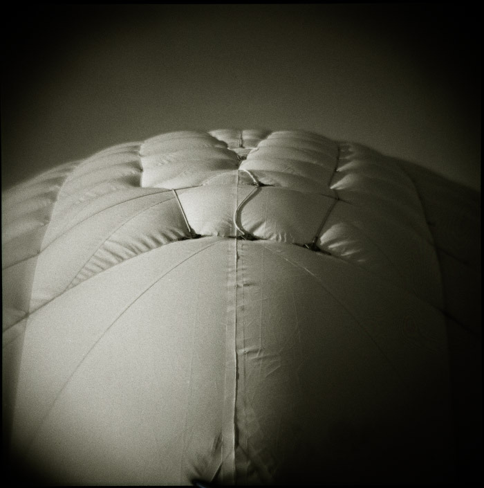
Note the vignetting at the corners of the image.
With all lenses, and particularly with cheaper (<$150) lenses, distortion and vignetting can be a big problem. Common distortion modes are where the X or Y axis appears to no longer be straight and perpendicular with each other (rectilinear). Often you will see an image look wavy or bulging. With vignetting the edges and particularly the corners become darkened. You can often reverse the effects of warping by using a homography for image rectification.
With any lens and camera system you need to check the mount types. There are many different styles for mounting a lens to a camera. Wikipedia has a long list of mounts that can be found here. The most common mount that I have seen for computer vision cameras (ie. no viewfinder and designed for machine vision applications) is the C mount. Choose a lens that you can lock into place. Not only should you be able to lock the lens into place you should be able to lock any rotating knobs into place (such as for zoom and focus). This is usually accomplished with set screws. I am not that familiar with them but I will note that there are many different filters that can be attached to your lens for things such as polarization and blocking certain parts of the spectrum (such as IR). Your iPhone camera typically has a built in IR filter in the lens to remove IR components from your images.
Another semi-obvious thing to look into is whether you need a black and white (often expressed as B&W, BW, or B/W) or color camera. In many cases B/W cameras will be easier for your algorithms to process. However having color can give you more channels for humans to look at and for algorithms to learn from. In addition to black and white, there are hyper spectral cameras that let you see various frequency bands. Some of the common spectral ranges that you might want are ultra-violet (UV), near-infrared (NIR), visible near-infrared (VisNIR), and infrared (IR). You will also want to pay attention to the Dynamic Range of the camera. The larger the dynamic range, the greater the light difference that can be handled within an image. If the robot is operating outdoors in sun and shade you might want to consider a high dynamic range (HDR) camera.

You will also want to consider the interface you have to the camera – both the electrical and software interface. On the electrical side, the common camera protocols are camera-link, USB2.0, USB3, firewire (IEEE1394), and gigabit ethernet (GigE). GigE cameras are nice since they just plug into an ethernet port making wiring easy. Many of them can use power-over-ethernet (PoE) so the power goes over the ethernet cable and you only have one cable to run. The downside of GigE is the latency and non deterministic nature of ethernet. The other interfaces might be better if latency is a problem. Also, you generally can only send full video over GigE with a wired connection, and not from a wireless connection. This is because you need to set the ethernet port to use jumbo packets, which can not be done on a standard wireless connection. Probably the most common reason I see GigE cameras not working properly is that the ethernet port on the computer is not configured for jumbo packets. For software, you want to make sure that your camera has an SDK that will be easy for you to use. If you are using ROS or OpenCV, you will want to verify that the drivers are good. You will also want to check what format the image is supplied back to you from the camera: will it be a raw image format? or will it be a file format such as png of jpg?
If you are doing stereo vision, you want to make sure the cameras have a triggering method, so that when you issue an image capture command you get images from both cameras simultaneously. The triggering can be in software or hardware, but hardware is typically better and faster. If you are having problems with your stereo algorithm this can be the source of the problem, especially if you are moving fast.
Finally, if you are looking for video, you also need to look out for the Frame Rate typically specified in Frames per Second (fps). This refers to how many images the camera can take in a second. We can then call that sequence of images a video.
Hope this helps. If you have camera experiences you would like to share – especially related to good/bad SDKs and what works/doesn’t-work with ROS – please share in the comments below.
While writing this post I saw Wikipedia said “MV is related to, though distinct from, computer vision.” This surprised me as I always viewed machine vision and computer vision to be similar fields, just different terms used in different industries. So I followed the references and found an interesting article from Bruce Batchelor here. After reading his article I am still not sure if I agree. I think there are people who are theorists that only care about the vision aspects, there are integrator’s who only care about the system and don’t know much about the vision aspects. However there is also a large segment in the middle, such as roboticists, that care about both sides of the problem. Working in robotics you need to care about the real world applications while also understanding the vision problems and develop new vision methods and techniques.
As roboticists are we doing both? are we only doing computer vision? only machine vision? What do you think? Leave your comments below.
For optics and some good technical notes you can visit Edmund Optics. They have a large supply of everything optics related.
Sources:
- http://www.gizmag.com/camera-lens-buying-guide/29141/
- http://vitaleartconservation.com/PDF/affects_of_lens_quality_on_image_resolution_v3a_draft.pdf
- http://www.gizmag.com/camera-lens-buying-guide/29141/
- http://digital.ni.com/public.nsf/allkb/1948AE3264ECF42E86257D00007305D5
- http://www.nikonusa.com/en/Learn-And-Explore/Article/g3cu6o2o/understanding-focal-length.html#!
- http://en.wikipedia.org/wiki/Angle_of_view
If you liked this article, you may also be interested in:
- Things to think about when transporting your robot
- Controlling a brushless DC motor with no encoders
- UMich team works on perception and localization using cameras
- Multi-viewpoint robotic camera system creates real ‘bullet time’ slow motion replays
See all the latest robotics news on Robohub, or sign up for our weekly newsletter.
tags: c-Education-DIY, tutorial, Vision


