Robohub.org
Where to place fuses and how to protect your robot and motors
 When you design a system it is often tempting to place a fuse on every component. This idea is fine for most batteries, sensors, and computers. However this can really cause destruction when you are working with motors. I have seen several motor drivers burn up (probably the FET’s got damaged) from having this set up wrong.
To start with the simple devices … having a fuse where the batteries enter the system is a good idea. After that I like to fuse each voltage rail (ie. DC-DC converter) so that we can take groups of sensors/computers offline at a time for testing as well as for the protection the fuses provide. I think fusing each bus is often a good compromise between fusing everything and fusing nothing.
The place where fusing gets tricky is with motors. To start, whenever you have a lot of energy (relative to your system) being converted from mechanical to electrical energy through your motor, a shunt regulator should be used. Any time your motors might be back driving, decelerating quickly, or dropping due to gravity (such as in a robotic arm) you have the potential for the voltage on your power bus to increase. When the voltage starts increasing you can burn out the components on your bus. For example if your motor controller is rated for 55V Maximum and you are driving a 48V motor, it is very easy for the back driving of the motor to raise the voltage above that maximum value. Remember Every motor is a generator; and every generator is a motor – it just depends which direction you spin it. The solution to this problem is to put a shunt regulator on your bus.
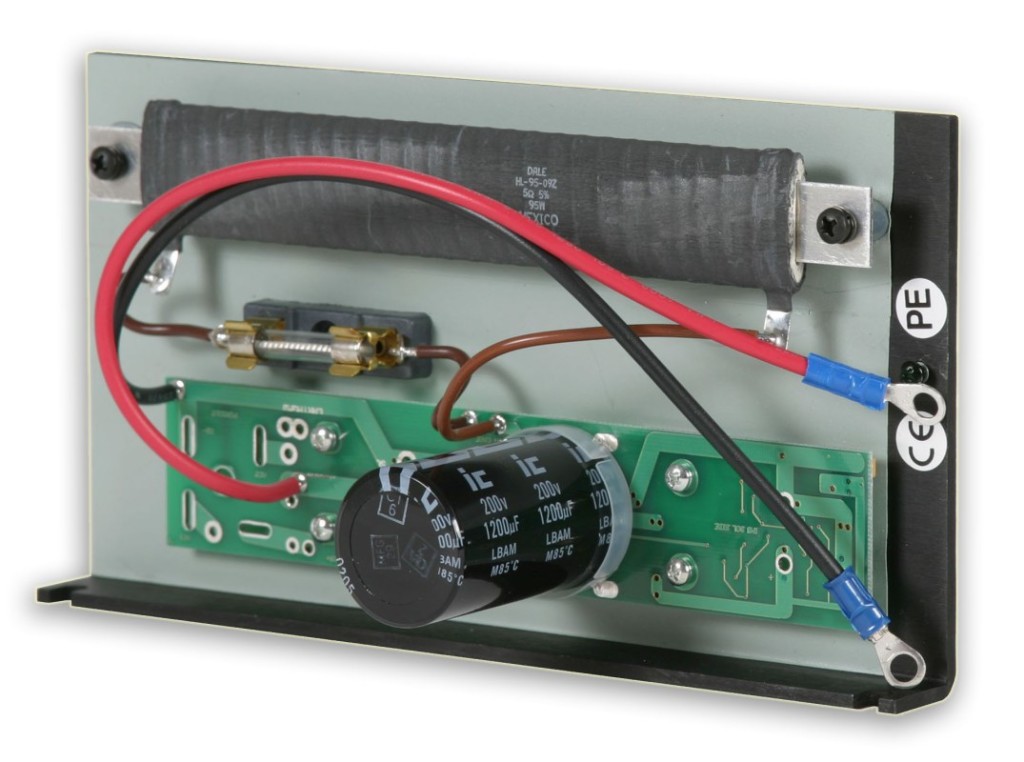
A shunt regulator is pretty much a big resistor that can shunt energy to ground in order to prevent the bus voltage from increasing to dangerous levels and destroying your robot. You generally want to set (or purchase) the shunt regulator at a value higher than the bus voltage. For example on a 48V motor you might want to set the shunt regulation voltage to 56V. One thing to be careful about is if your motors are on the main bus with the batteries, and you are charging the batteries in place, then the bus voltage increases from the charger. The shunt regulator voltage setpoint must be higher than the highest voltage that your battery charger will use while charging the batteries. Wiring the shunt regulator is super-simple. All you need to do is run two wires to the positive and ground rails of the power bus that you are trying to protect.
It’s common to go ahead and put a fuse before each motor driver (and its motor), and put the shunt regulator on the main bus (with no fuse). This looks pretty but you just set yourself up for problems: if the fuse blows, the amplifier is now disconnected from the shunt regulator, allowing the voltage to increase on that segment and destroy your motor (and driver)!
So what is the solution? There are generally two approaches:
- Do not fuse each motor driver individually. This lets you put all your motors and the shunt regulator on the same segment, so that if the fuse blows there is still a path to the shunt regulator.
- Fuse each motor driver separately. However you put a power diode across the fuse to allow current to flow from the motor amplifier to your main bus where the shunt regulator is.
There are two other approaches for this that are seldom used in robotics.
- You can put a shunt regulator next to each motor driver, but this is often not done due to cost and volume.
- You can increase the capacitance of your power supply/system, allowing it to store more energy.
When you choose the value for the fuse there are generally two approaches:
- Choose the value based on what you expect currents to be (plus some margin).
- Select a fuse based on protecting a device from the maximum current that will destroy it.
When you select fuses for a motor you will often want to use the second method of selecting a fuse just to avoid having to deal with voltage spikes blowing fuses. An example of when you might want the first option is if you want to limit current so something will not damage its environment if things go bad. You will also usually want to get a slow blow fuse and not a fast or quick blow fuse. This will give a little extra margin before the fuse blows to handle small transients.
There are several places to purchase shunt regulators from. Two of the common sources are Maxon Motors and Advanced Motion Controls. In some cases you can get a shunt regulator integrated into your motor driver, for example Galil Motion Control has some nice (and inexpensive) integrated options.
Here is an interesting app note from Galil Motion Control about computing voltage increases.
Main image is from Advanced Motion Controls.
tags: c-Education-DIY, tutorial


