
Robohub.org
The Distributed Flight Array: Modular robots that self-assemble, coordinate and take flight
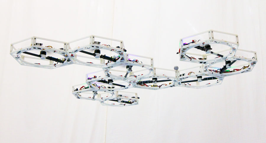
“The whole is greater than the sum of its parts” — a catch phrase that aptly expresses the Distributed Flight Array: a modular robot consisting of hexagonal-shaped single-rotor units that can take on just about any shape or form. Although each unit is capable of generating enough thrust to lift itself off the ground, on its own it is incapable of flight much like a helicopter cannot fly without its tail rotor. However, when joined together, these units evolve into a sophisticated multi-rotor system capable of coordinated flight and much more.
In the beginning
In the summer of 2008, Professor Raffaello D’Andrea at the Institute for Dynamic Systems and Control at ETH Zurich envisioned an art installation consisting of single-rotor robotic units that would self-assemble on the ground and then perform a joint task that would otherwise be impossible to achieve on its own — flight. This modular flying vehicle would then break apart in the air and then repeat the process over again, but in a new randomly-generated configuration.
Feasibility study
The number of challenges faced in designing and implementing such a system are many. We first wanted to be sure, however, that the concept was indeed feasible. Making some realistic assumptions about the system we performed some back-of-the-envelope calculations and created a linear dynamics model of the vehicle in order to provide us with some intuition about its physical dynamics. From this, a control strategy was devised. We then simulated the closed-loop system under a variety of disturbances, providing us with a general understanding of the physical requirements needed to successfully execute the project.
Design and implementation of the physical system began in the fall of 2008 as part of a design project class at ETH Zurich. The class consisted of eight graduate-level students from mechanical, electrical, and software engineering, as well as technical staff and instructors, including myself. Our task was to design and build a functional prototype that would demonstrate three key abilities of the system: (1) docking, (2) coordinated ground mobility, and (3) coordinated flight. In accomplishing each of these tasks, we would in turn validate our model and control strategy, and likely discover limitations to the system we did not foresee.
The project was no doubt challenging, and the timing constraints imposed by the class did not work in our favour. Our initial hope was to demonstrate each of the key abilities using a single set of vehicles and to demonstrate coordinated flight in several configurations. Our goals were too ambitious under the framework of this class and therefore loosened our requirements. By the summer of 2009 (a few months after the class had ended), we succeeded in demonstrating each of these key abilities, and ultimately, the project’s feasibility.
Towards the end of the above video, you will notice one of the many limitations of the system: its inability to control its altitude (or height off the ground). You may also notice that both flying and driving capabilities were separated in order to make the vehicle lighter for flight. Its primary limitation, however, was its inability to demonstrate coordinated mobility for randomly assembled configurations. The units themselves lacked the ability to communicate on each of their sides, and even if this were possible, we did not yet have any way of automatically generating the appropriate control strategy for the assembled configuration. For our demonstration, each unit was pre-programmed for a particular configuration and the controller was tuned by hand. This, however, was just the tip of the iceberg for the long list of requirements needed to successfully achieve our final goal.
Design iterations
With the design project class under wraps, and feasibility of the system demonstrated, the next step was to engineer a truly modular system capable of coordinated mobility — both on the ground and in the air. This was by no means a straightforward process; if it was, it wouldn’t be considered research. One additional revision of the vehicle was created prior to arriving at the current design.
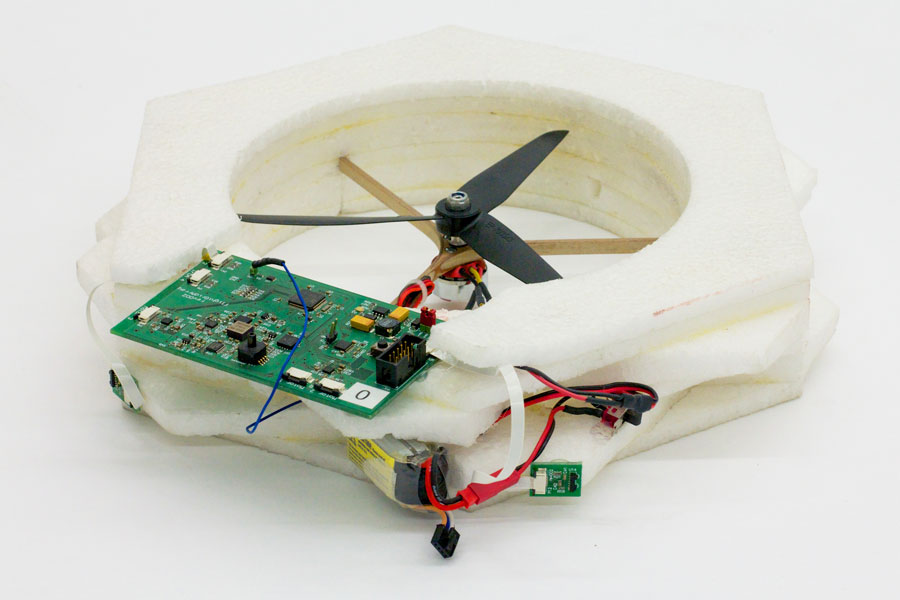
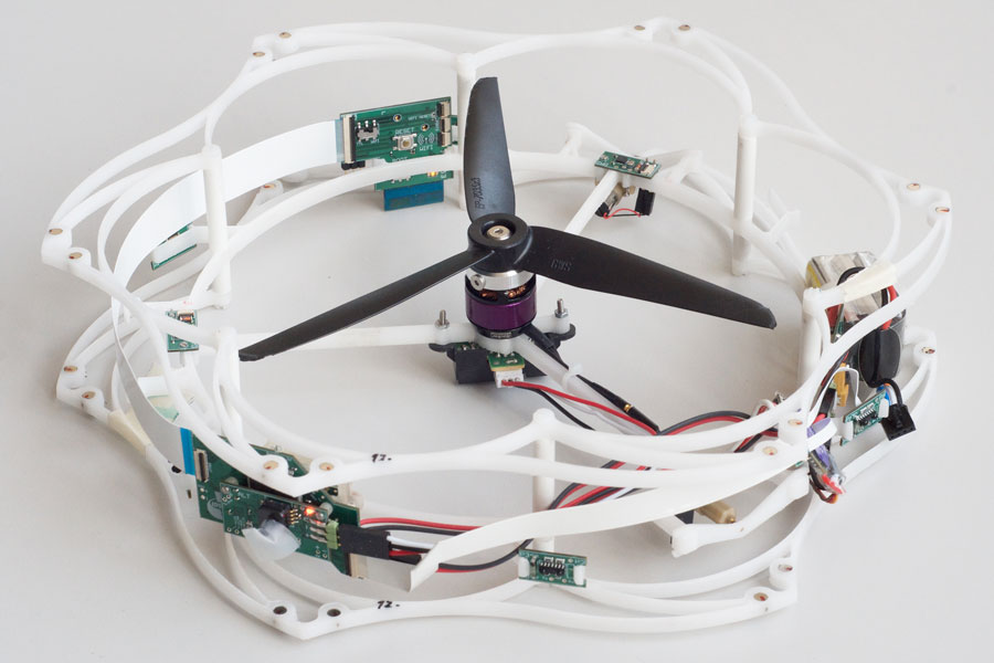
In designing Revision 1, one of our major goals was to integrate both driving and flying capabilities. This required us to rethink the mechanical chassis and to design with a sufficient thrust to weight ratio in mind. Although light-weight and mechanically robust, the ethyl polypropylene foam chassis we used in the proof-of-concept vehicle was difficult to manufacture and our experience led us to switch to a different material. We opted instead for constructing the chassis out of laser-cut acetal plastic, a higher-powered flight motor, and a new propeller. This resulted in a very robust chassis, which was easy to fabricate in-house, and it provided sufficient thrust for the purposes of lift and control effort. What we failed to consider, however, was the stiffness of the chassis and manufacturing variability of the rotors. Only after completing the design of Revision 1 and producing several units did we discover that the vibrating modes in the chassis caused by aerodynamic turbulence from the propellers saturated the onboard rate-gyroscope sensors, which was needed for closed-loop control.
It was also important in this revision to demonstrate communication on each of its six sides. We successfully accomplished this using infrared transceivers mounted to each connection interface. However, we later discovered interference issues when conducting experiments with our vehicle within the environment of a 3D motion capture system (needed for ground truth measurements), which uses a similar frequency of infrared light to illuminate markers that it tracks in order to estimate the pose for the object of interest.
On top of this was the need to shrink the size of the electronics such that it would fit within the protected volume of the chassis. We were motivated by recent manufacturing possibilities in creating flexible printed circuit boards, and locked on to this scheme. When it came around to producing the boards, however, the lead-time for such services in relatively small quantities was much too long for our requirements — we wanted to be able to prototype and have a quick turn-around on our designs. We therefore had to redo parts of the design for a standard printed circuit board.
There was also the suggestion to first fly the system using a 3D motion capture system for measurement feedback. Since these measurements were very precise and relatively fast, we could by-pass the onboard estimation problem and focus only on the control problem. This, in fact, worked against us for two major reasons: (1) as described before, the infrared light from the 3D motion capture system interfered with inter-communication; and (2) measurement information (or control information) needed to be transmitted to the vehicle wirelessly for control purposes, which at the time of development (using WiFi) generally incurred a lot of latency and packet loss.
There was a lot that needed to be redesigned, a lot that was assumed, and there was pressure to get research publications out. In Revision 1, we tried to jump over too many hurdles at once and what we delivered was a semi-functional system — functional under optimal operating conditions, but failed to work most of the time. However we learned many things, in particular it focused our attention on parts of the design that we overlooked. This laid the ground work for Revision 2.
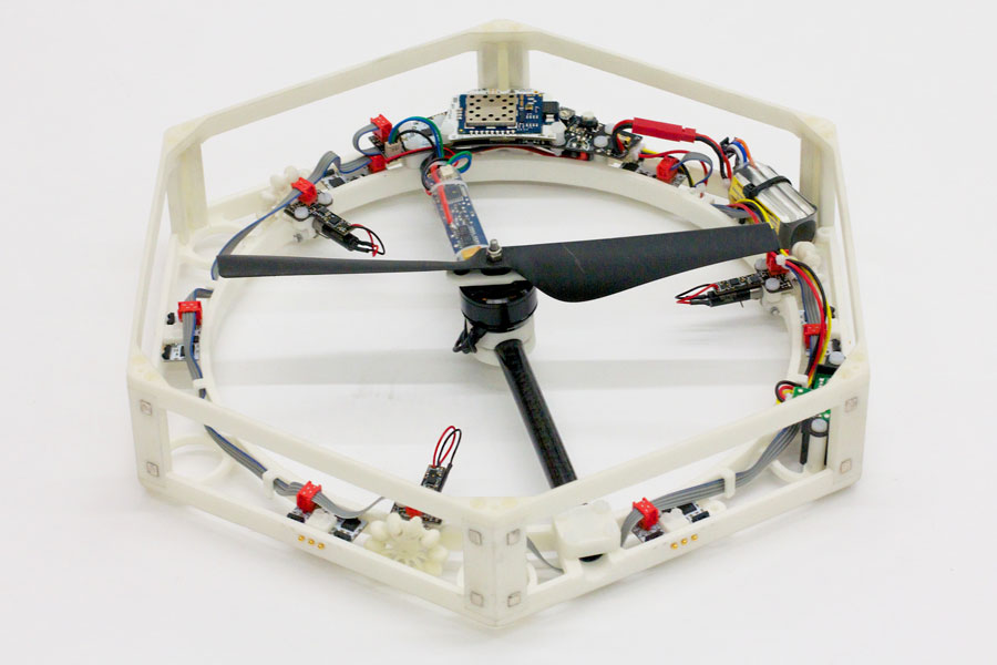
In Revision 2, we redesigned the chassis and thrust generation unit (i.e. propeller and flight motor) from scratch, but kept most of the power and control electronics the same. Using some of the most recent advances in manufacturing technology, the chassis was 3D printed this time around, enabling us to design with very little fabrication constraints and has a relatively quick turn-around time. The first factor was very important because of the number of tightly integrated components held together within a single unit. The second factor enabled us to quickly test a design and re-iterate as necessary.
This time around, we stepped through each phase of the design systematically. The new flight motor and propeller was tested to ensure that it produced a sufficient amount of thrust and produced little vibration within the chassis, which we tested using the rate-gyroscope sensors from Revision 1. Using two units and electronics from Revision 1, we tested the closed-loop behaviour around a single axis of rotation by mounting the two units on a horizontal pivot. This alone required a few iterations of the chassis, which in the end we managed to get right.
Ignoring the intercommunication problem, we ploughed ahead and constructed six complete units for flight. In this revision, we demonstrated coordinated flight for a variety of configurations. The flight controller was computed ahead of time and sent wirelessly to each unit prior to flight.
Knowing that the chassis and thrust generation unit was sound, we then went ahead and integrated driving capabilities and intercommunication into the units. In terms of the latter, we redesigned the intercommunication scheme, employing a hard-wired interface instead of an infrared wireless link and utilized an electrical bus to clean up the mess of communication lines we had in Revision 1. A detailed description is given in the next section.
Designed from the ground up
Each unit uses a single 32-bit 72 MHz microcontroller to interface with all of the onboard sensors, actuators, and communication peripherals. The same microcontroller is also used for performing all of the computation necessary for estimation and control — there is no computation that is performed offboard. An interchangeable wireless module (either WiFi or proprietary frequency hopping spread spectrum) allows us to communicate with each unit (e.g. telemetry and user commands); in the case where external sensors are used (e.g. 3D motion capture system), the data can be sent to the units over this wireless link.
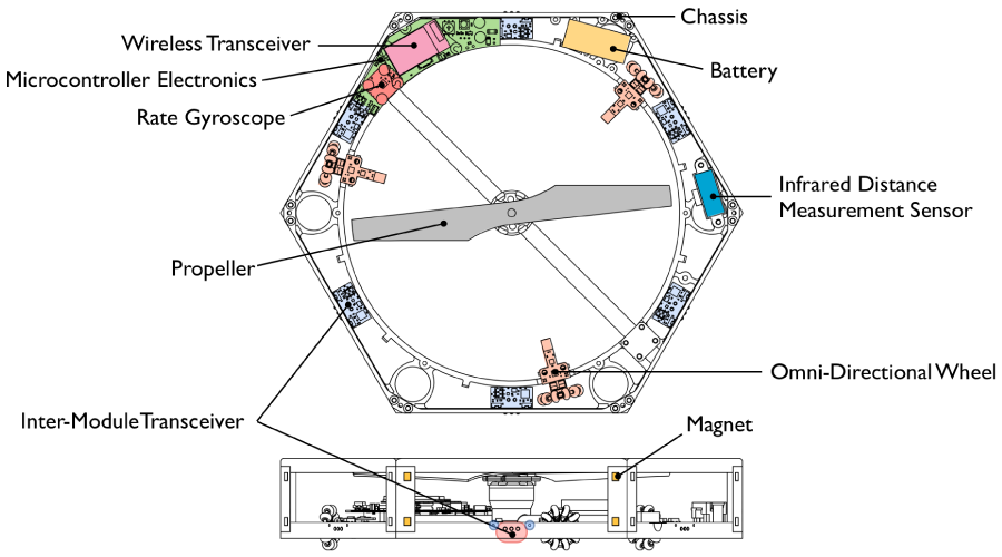
Standard on most aerial vehicles is a 3-axis rate-gyroscope, which is used for measuring body angular velocities, as well as estimating the attitude of the vehicle in flight. An infrared distance measurement sensor is used for measuring the distance of a unit to the ground. Not only is this used for estimating the altitude of the vehicle, but if units share their distance measurements with one another they can also estimate the vehicle’s tilt when flying over a flat surface.
We have designed each unit with magnetic interfaces, located along each of its six sides. This allows a unit to passively self-align with its connected peers. The connection strength, however, is in fact not very strong. This was intentional, as it clearly demonstrates the need for cooperation between individual units in order to achieve flight — without it, the vehicle would simple rip itself apart before take-off. To successfully accomplish this, the flight control strategy must minimize the shear forces occuring between interconnected units during flight.
Also located on each of its six sides are three gold push-pins. Together with the magnets, this interface behaves similarly to the Apple MagSafe power connector, except that this interface is used to provide a means for hard-wire communication between neighbouring peers. With this, we developed our own network layer to handle inter-unit communication, as well as algorithms for routing packets, time synchronization, information fusion, etc. on a resource limited embedded system. Units are also able to communicate with one another in plane at a distance using infrared wireless transceivers, which is primarily employed for self-assembly purposes.
Each unit is equipped with three omni-directional wheels, allowing it to move on the ground with a high degree of maneuverability and to be able to move when assembled together. One of the nice things about using 3D printer technology is that the omni-wheels could be printed as a single piece, without having to assemble any components.
Positioned at its centre is a fixed-pitch propeller, capable of generating enough thrust to lift a single unit off the ground. All units are physically identical except for the handedness of its propeller. Some are clockwise and some are counterclockwise — this is needed in order to cancel out the aerodynamic torques in flight. Finally, a high energy-density Lithium-Ion Polymer battery is used to power all the electronics and actuators contained onboard.
Coordinated flight
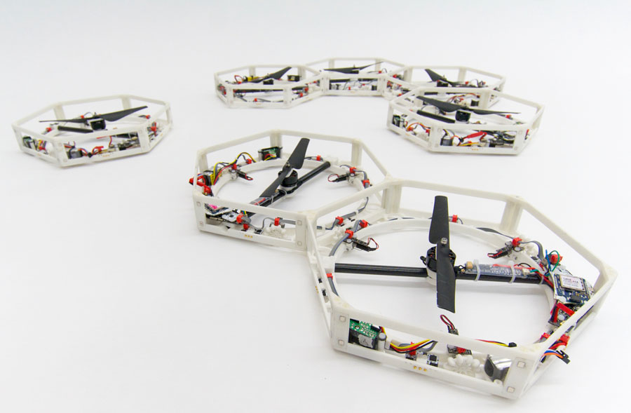
The units can move around on the ground, self-assemble, generate an adhoc mesh network in order to communicate with one another, but the most striking feature of the Distributed Flight Array is its ability to fly in an unlimited number of configurations.
Recall that the units are being held weakly together with magnets. Thus, each unit is generating the appropriate control effort necessary to keep the vehicle in flight while minimizing the shear forces between individual units. What is most surprising is that the units themselves do not necessarily need to communicate with one another during flight.
The only information that a unit needs for flight is its local sensor data and its position with respect to the vehicle’s centre of mass. This can be computed if each unit knows the physical configuration of the vehicle. In order for a unit to determine this on its own, each unit can work out its relation to neighbouring units by sharing appropriate information. By forwarding this information around the network, each unit can arrive at the physical configuration of the vehicle, much like how one might establish his/her family tree.
Assuming a rigid body for the vehicle, which was taken into account when designing the chassis, local sensor information provides a unit with a rough estimate of the vehicle’s tilt and altitude. And knowing its position with respect to the centre of mass, it’s straightforward to work out the appropriate control effort needed to counter-act any disturbances. We avoided using a linear quadratic regulator or other optimal control strategies in favour of something much more straightforward, and as it turns out the method is also scalable. We employ a cascaded parameterized controller, consisting of tuning parameter that are physically intuitive (i.e. closed-loop natural frequency and damping ratio) for each degree of freedom.
Now, it wouldn’t be reasonable to hand-tune the controller for each and every configuration. We instead developed a means for automatically computing the tuning parameters for any flight-feasible configuration of the vehicle that would result in best flight performance. In carefullly analyzing the parameters obtained for a variety of configurations, we then developed a scalable method for mapping the configuration of a vehicle to its approximated optimal control tuning parameters.
Rewards and reality
A lot challenges, a lot of frustration, but also a lot of reward. What started as an idea is now a reality. Although we have not necessarily shown it to reenact the Concept Animation shown above, it is certainly capable of performing each of those tasks. What we have here is a piece that suitably demonstrates cooperative behaviour.
The success of this project would not have been made possible without support from the Swiss National Science Foundation, as well as the countless number of hours spent by students and technical staff — they all deserve as much credit. The Distributed Flight Array is currently being used at the Institute for Dynamic Systems and Control at ETH Zurich as a modular robotics platform for investigating algorithms in distributed estimation and control. Updates regarding the project’s status and a list of those involved with the project can be found on its home page.
Who’s Currently Involved: Raffaello D’Andrea, Maximilian Kriegleder, Igor Thommen, and Marc A. Corzillius
Photo credit: Raymond Oung
Note: This post is part of our Swiss Robots Series. If you’d like to submit a robot to this series, or to a series for another country, please get in touch at info[@]robohub.org.
If you liked this article, you may also be interested in:
- Insect-inspired flying robot handles collisions, goes where other robots can’t
- The Distributed Flight Array: Modular robots that self-assemble, coordinate and take flight
- Designed to mingle: Rezero ballbot’s smooth moves can handle a crowd
- Cubli – A cube that can jump up, balance, and walk across your desk
See all the latest robotics news on Robohub, or sign up for our weekly newsletter.
tags: c-Research-Innovation, cx-Aerial, ETH Zurich, Research, Swiss Robots, Switzerland