
Robohub.org
Putting humanoid robots in contact with their environment
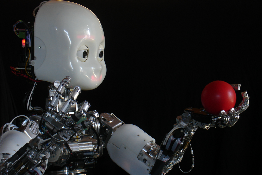
iCub (Image credit: Istituto Italiano di Tecnologia)
In this article, our humanoid robot iCub is put to the test using manipulation and interaction as sources of knowledge and new experience, as well as, providing a means to explore and control the environment. The design specifications of the iCub turn it into a physical container for neuroscience methods.
by Francesco Nori, Silvio Traversaro, Jorhabib Eljaik, Francesco Romano, Andrea Del Prete and Daniele Pucci
Back in 1961, the first industrial robot was operating on a General Motors assembly line. Its name was Unimate. It was fixed to the ground while it accomplished its task of transporting die castings and welding them on car bodies. More than half a century later, robots have come a long way, yet their most common use remains in that sector, for the most part, fixed to the ground (or some other part of the plant) almost caged away from humans as to not represent any danger. Interaction control (e.g., object manipulation) in these robots is usually achieved separately from whole-body posture control (e.g., balancing). If robots are thought to be present in our everyday lives and move in unstructured environments, interaction and posture control must be reconciled. A robot that can freely move in the environment is known as a free-floating base mechanism.
At the Italian Institute of Technology (IIT) in Genoa, Italy, we strongly believe in manipulation and interaction as sources of knowledge and new experience as well as means to explore and control the environment. A humanoid must then act on the environment to know it. The peculiar design specifications of our humanoid robot iCub turn it into a physical container for neuroscience methods. Our work takes advantage of its associated specificities and lays out the main building blocks that permit the implementation and integration of a system for balance and motion control of a humanoid robot. These components are namely, the low level joint-torque control, the task-space inverse dynamics control, the task-planner and contact forces and joint-torques estimator. These are seen as fundamental composing elements to effectively obtain such system on a real platform.
iCub is 104 cm tall and has 53 degrees of freedom: 6 in the head, 16 in each arm, 3 in the torso, and 6 in each leg. All joints but the hands and head are controlled by brushless electric motors coupled with harmonic drive gears. Custom-made Force/Torque (F/T) sensors are mounted in both iCub’s arms, between the shoulders and elbows, in both legs between the knees and hip and between the ankles and feet (see Figure 1). In addition, iCub is endowed with a compliant distributed pressure sensor (robot skin) composed by a flexible printed circuit board (PCB) covered with a layer of an elastic fabric further enveloped in a thin conductive layer. The PCB is composed by triangular modules of 10 taxels, which act as capacitance gages with temperature sensors for drift compensation.
As a general overview, our main goal is to keep our robot at a given configuration (posture) while being able to cope with multiple contacts. In order to do so, we first need to know where in its body are contacts happening, but not only! Also the forces and torques (a.k.a. wrenches) at those points are needed if we want to maintain contact stability (the robot skin gives us only the location of the contact). A robot can exert a particular force by making its DC motors provide the torques that generate a desired wrench at the point of contact.
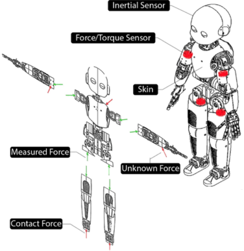
Figure 1. Overview of iCub’s sensor set and their location. Measured and possible contact forces are depicted as well. On the left it is shown how iCub is “broken apart” for the estimation of external and internal wrenches.
The main components of this system are namely, the low level joint-torque control, the task-space inverse dynamics control, the task-planner and contact forces and joint-torques estimator. These are seen as fundamental composing elements to effectively obtain balance and motion control on a platform. In particular, the task-space inverse dynamics controller is used for finding those torques that satisfy the body posture and contact stability tasks knowing what the current joint torques are, along with the wrenches at the points of contact. Figure 2 shows the general workflow of the system.
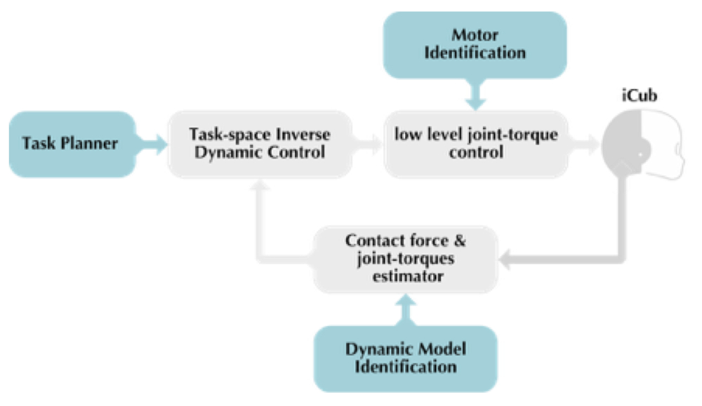
Figure 2. Workflow for iCub’s balance and motion control system. Light blue blocks are “offline” components of the system.
Let us now give a little more of insight into the different blocks composing this framework. Contact wrenches on iCub are estimated, not directly measured. This is done exploiting the embedded F/T sensors and the skin, in conjunction with the velocity, acceleration and inertial information of the links. If the robot is treated like multiple branches cut at the location of the F/T sensors (see Figure 1), for each of them we can formulate Newton’s and Euler’s equations and solve for the unknown contact wrenches. An exact estimate for a specific branch of the robot is given when only one contact happens, otherwise the algorithm tries to give the best estimate possible for each contact among the infinitely many solutions. Once these external wrenches are known, this information can be propagated recursively to estimate also the internal wrenches (between links) and finally the joint torques. In this way, iCub does not need to use joint-torque sensors.
The joint-torque control block (in Figure 2) uses the estimated joint torques and compensates for friction to guarantee that each motor provides the desired amount of torque, as commanded by the task-space inverse dynamic control block.
All the elements that have been mentioned until now use values that are usually provided by a computer aided design (CAD) software, such as the links’ centers of mass or their mass inertias.
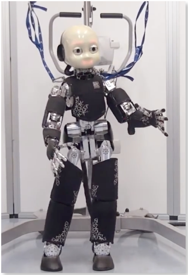
Figure 3. iCub moving its center of mass from left to right while maintaining balance.
Special attention must be paid to these parameters, since they are usually not accurate enough, making the job of the task-space inverse dynamic control block much harder. A somewhat similar problem occurs in the low level joint-torque control block, since it relates through a mathematical model the voltage that must be given to the motors and a desired output torque, also taking into account the presence of friction. The amount of friction changes from one joint to another. The parameters that characterise friction (friction coefficients) and the dynamical parameters of the robot are thus identified and tuned. These are the jobs of the Dynamic model identification and the Motor Identification block respectively.
![FIGURE 4. Results of the double-support experiment on planar contacts (left and right feet). The picture shows the time behavior of forces (top) and center of mass position (bottom) on the sagital (blue) and transverse (green) axis. It is worth noting that forces should be proportional to center of mass accelerations and this is visible in the plot considering that accelerations are sinusoidal in counter phase with positions. Rapid variations of the contact forces at the time t = 2[s], i.e., starting time, are due to the activation of the torque control.](http://robohub.org/wp-content/uploads/2016/08/graph-journal4.jpg)
Figure 4. Results of the double-support experiment on planar contacts (left and right feet). The picture shows the time behavior of forces (top) and center of mass position (bottom) on the sagital (blue) and transverse (green) axis. It is worth noting that forces should be proportional to center of mass accelerations and this is visible in the plot considering that accelerations are sinusoidal in counter phase with positions. Rapid variations of the contact forces at the time t = 2[s], i.e., starting time, are due to the activation of the torque control.
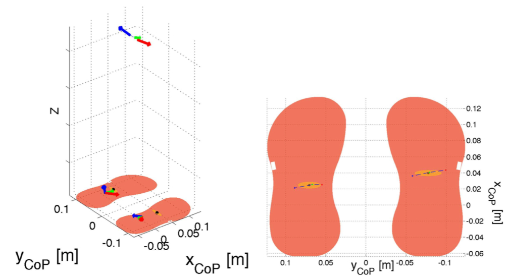
Figure 5. Results of the double-support experiment on planar contacts (left and right feet). The left picture shows in three dimensions the feet contacts, the feet center of pressures, the forces at the feet and at the center of mass during three instants: at two extrema of the sinusoid (red and blue) and in the middle of the sinusoid (green). Remarkably forces are maximum at the extrema when also accelerations are maximal. The right picture shows a close-up of the feet with the trajectory of the center of pressure, an ellipse representing a Gaussian fit of the data points and three points corresponding to the position of the centers of pressure when at the two extrema of the sinusoid (red and blue) and in the middle of the sinusoid (green).
At this point we are left with the commander in chief, the Task-space Inverse Dynamic Control block. The framework that has been adopted computes the joint torques to match as close as possible the desired contact forces while being compatible with the system dynamics and contact constraints all tailored to suit floating-base mechanisms. This set of force tasks is assigned a maximum priority, while others tasks can still be specified as long as they don’t enter in conflict with the higher-priority tasks. In the case of iCub standing on the ground and interacting with its two arms, these tasks correspond to the right and left foot wrenches that regulate the interaction with the floor and similarly for the two arms, with a final postural task to maintain the robot joints as close as possible to a certain reference posture. These references are indirectly computed such that they follow a desired trajectory of the center of mass while the robot’s angular momentum is reduced. Figure 3 is a snapshot of iCub following a sinusoidal trajectory for its center of mass, while maintaining balance exerting the appropriate forces on the two points of contact, namely, its two feet. Figures 4 and 5 show the results of this double-support (two feet in contact) experiment on planar contacts.
For more information see the original research paper:
Nori F, Traversaro S, Eljaik J, Romano F, Del Prete A and Pucci D (2015) iCub whole-body control through force regulation on rigid non-coplanar contacts. Front. Robot. AI 2:6. doi: 10.3389/frobt.2015.00006.
Additional references:
Metta, G., Natale, L., Nori, F., Sandini, G., Vernon, D., Fadiga, L., von Hofsten C., Santos-Victor, J., Bernardino, A. and Montesano, L., The iCub Humanoid Robot: An Open-Systems Platform for Research in Cognitive Development, Neural Networks, Volume 23, pp. 1125-1134, 2010.
If you liked this article, you might also be interested in:
- Robotic research: Are we applying the scientific method?
- Repeatable robotics: Standards and benchmarks from frontier science to applied technology
- Towards standardized experiments in human robot interactions
- Gestures improve communication – even with robots
See all the latest robotics news on Robohub, or sign up for our weekly newsletter.
tags: c-Research-Innovation, iCub
AUAI is supported by: