
Robohub.org
Make your own Dtto Modular Robot – Assembly instructions (Part 3 of 3)
Source: Alberto Molina
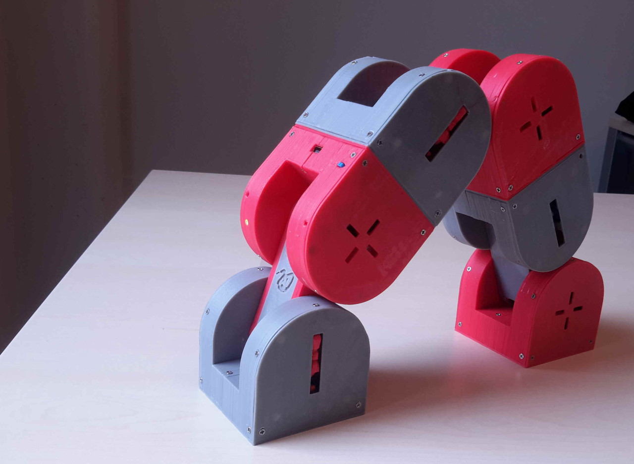
Dtto v2.0 is a modular self-reconfigurable robot focused on bio-inspired locomotion mechanisms. This tutorial shows how to assemble a fully working Dtto Modular Robot module.
Please review Parts 1 and 2 before getting started.
This document is an illustrated guide on how to assemble a module (v2) for the Dtto Modular Robot: https://hackaday.io/project/9976-dtto-v20-modular-robot
Now, let’s jump in for Part 3!
Step 15
We need:
- 1 x LM317 Voltage Regulator
- 1 x 1200 Ohm Resistor
- 1 x 330 Ohm Resistor
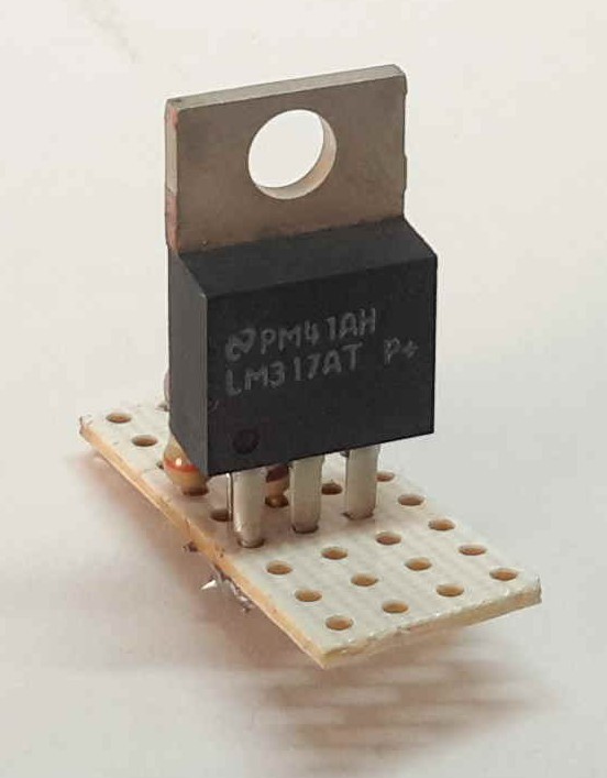
Now we will configure our voltage regulator. Since we basically need the regulator for powering the servomotors, and since they can operate between 5 and 6 volts, set the regulator to as close to 6 volts as you can. You can use any other voltage regulator you want, considering the minimum current needs.
The LM317 Voltage regulator allows us to adjust the output voltage using some resistors. You can find the details and the math in its datasheet, widely available. Refer to the datasheet to be sure of the connections. The resistors that we choose were 330 and 1200 Ohms, resulting 5.8 volts. We can also use 100 and 390 Ohms, resulting in 6.1 volts. Check the schematics.
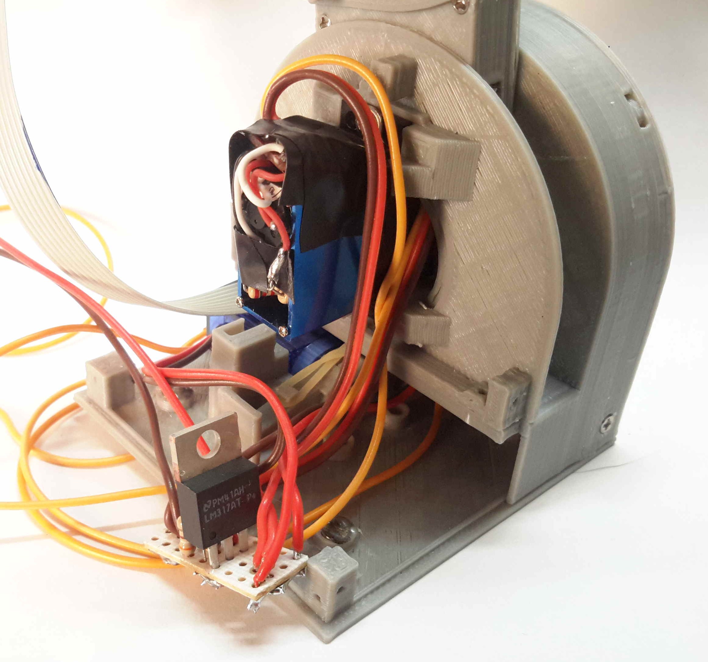
We need to power 5 servomotors with the output voltage from the regulator, so we need a small board to solder up the regulator, the resistors, and the cables. The dimensions of the board shouldn’t exceed 1*2.2cm, and it should fit in the module, as in the next pictures.
Check the schematics of the module, you can use the board to connect the cables that come from the batteries (switch), and the ones that connect to the Arduino.
Step 16
We need:
- 1 x Mini Switch
Now we are going to put a little switch to power on/off the entire module. Check the schematics.
For now, we’ll leave the switch hanging around and we will return to it later.
Step 17
We need:
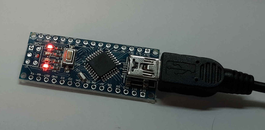
- 1 x Arduino Nano v3.0
The Arduino Nano is the brain of our module, our robot. It is very important to test the Arduino before proceeding to the following steps.
In this step, we will test the Arduino Board and the connection with the computer and will program an example program: blink. Once tested, note that, in order to save some valuable space, we will need a pins-free board.
Now put the Arduino Nano into the module.

Step 18
We need:
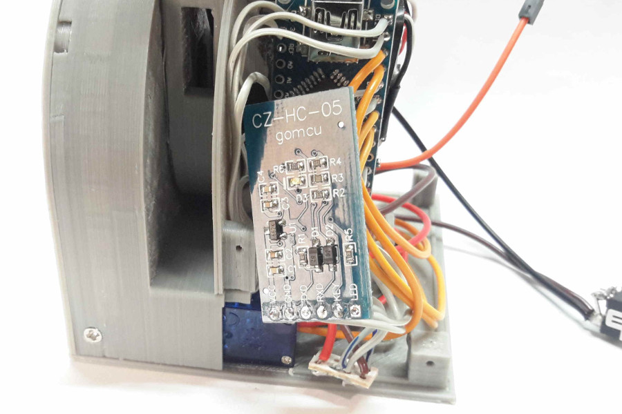
- 1 x HC-05 Bluetooth module (step 11)
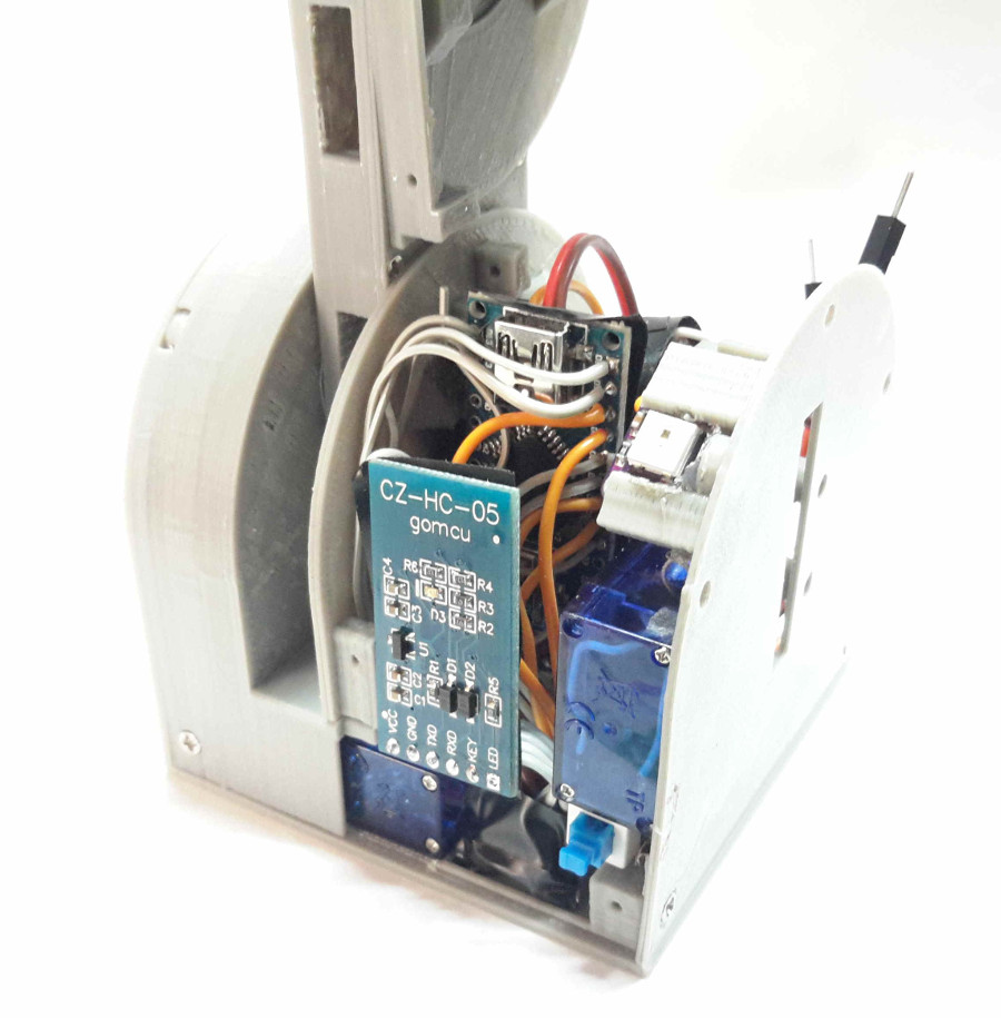
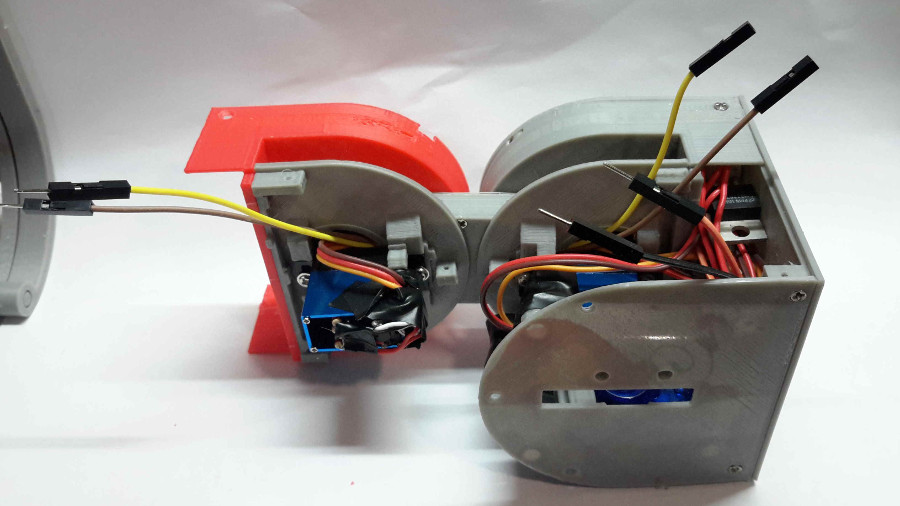
Now we are going to solder all the cables directly to the Arduino. Follow the schematics and try to keep the cables as short as possible. This is a tricky part, so you have to think how to put the cables to reduce length, allow all the components to fit, and allow the coupling mechanisms to work.
Check the schematics.
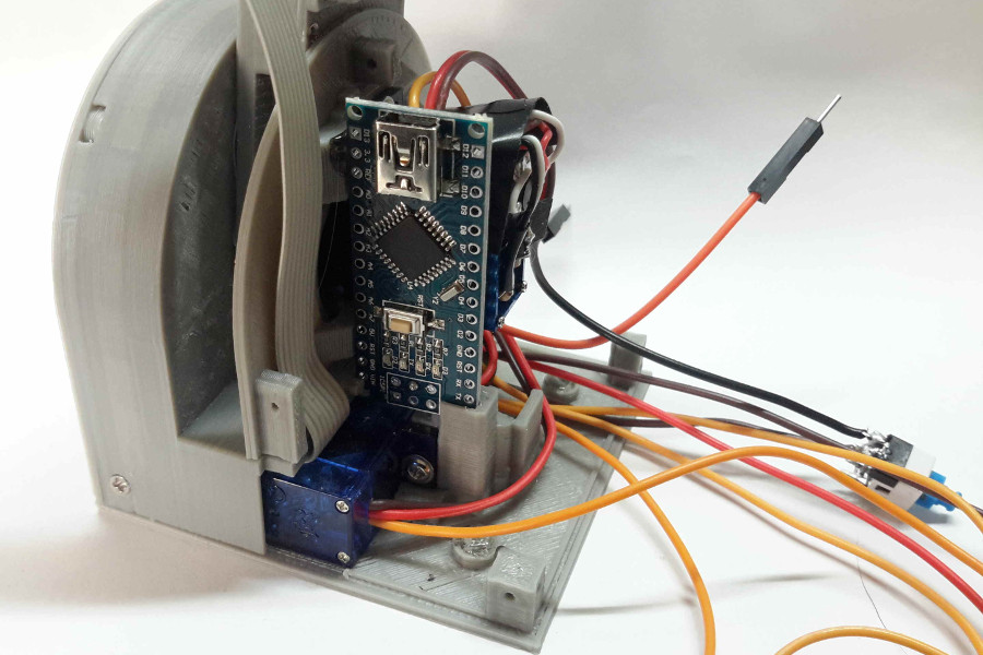
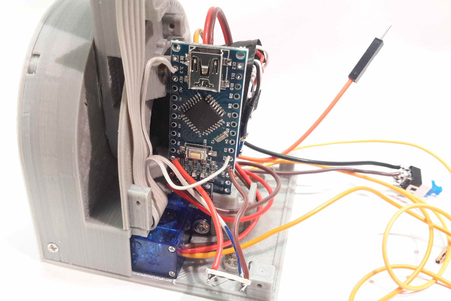
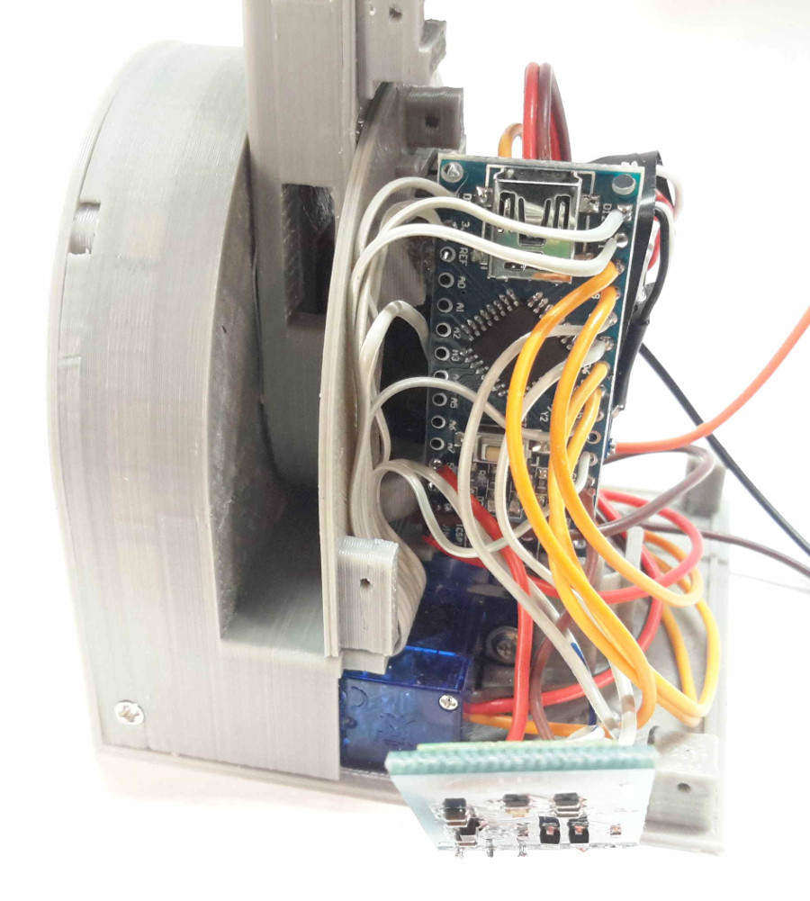
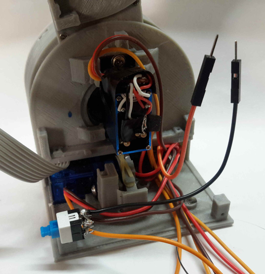
As you can see in the pictures, the Bluetooth module is “floating”. Since it’s on top of the Arduino, and we have to ensure that we can access the Arduino, cut the cables long enough. We’ve also used auxiliary boards to solder some cables together (grounds, etc.), for better cable organization.
Step 19
We need:
- 1 x WS2812 RGB LED
- 1 x Part 007-1 (step 10)
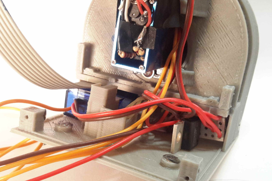
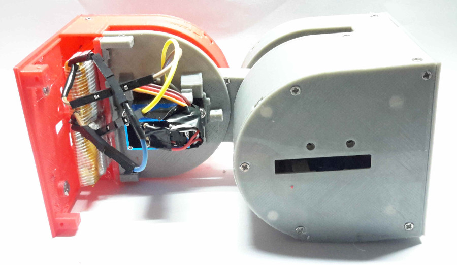
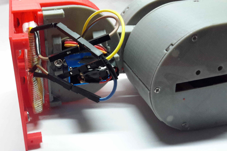
In this step, we will be mounting the fancy RGB LED of the robot. Cut the LED support to adapt it to the mounted LED. The cables should go, as in the picture (Note: the servo in this picture has no cables, we ran out of working ones).
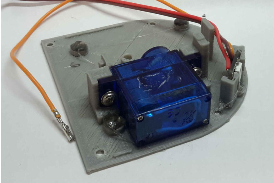
Now it’s time to fix the printed part to the module body, using 2 screws. As you can see in the picture, the mini switch is just under the servo we just assembled. Stick the mini switch in a position that, when pressed, it doesn’t protrude from the module.
Step 20
We need:
- 1 x Part 003-1
- 1 x Part 006-1
- 1 x Part 008-1
- 1 x Part 010-1
- 2 x Li-Po Batteries
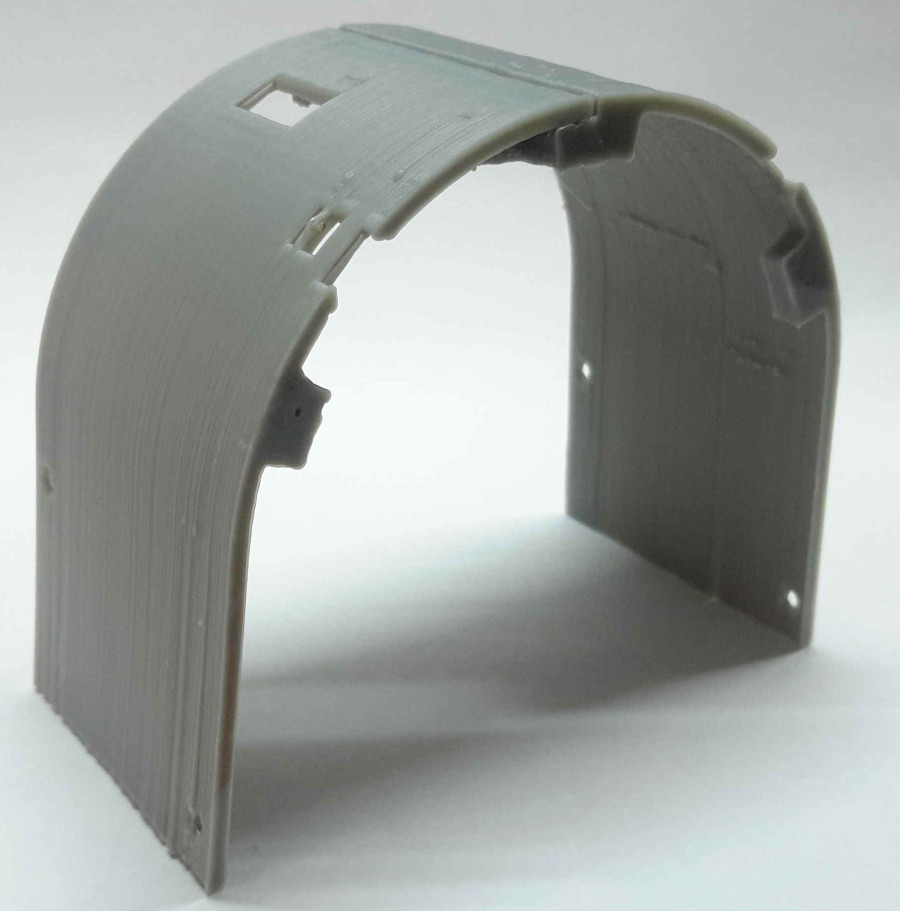
Just as we did in step 6, assemble part 003-1 to the other half of the module. Make sure that it rotates nice and easy.
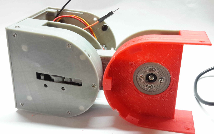
Now that the module is almost assembled, think about where to put the batteries. The module is designed to host the batteries in the male part, at the back of the Arduino, but since we are not using the empty space in the female part, we are going to put the batteries in the female half. This way we get a better weight distribution.
First, put the cables through that will power up the system:
Then, mount Parts 006-1 and 008-1, just as we did in the other half. Once we have done this, we can proceed to insert the batteries. Stick them in like in the pictures:
We can now mount the Part 010-1.
Step 21
We need:
- 2 x Part 001-1
- 2 x Part 002-1
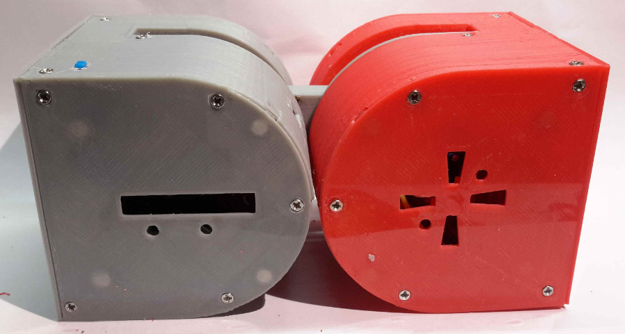
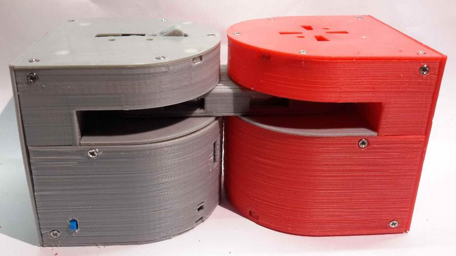
This is the final step and we are going to assemble the last parts.
First, test if they fit correctly. If not, sand down until you get them to fit nicely.
And this is the final result!
Now just program the Arduino with the available code and enjoy!
If you have any questions don’t hesitate to contact me, otrebla333@gmail.com.
Good luck with your modular projects!
This project and all of its files, images and texts are entirely licensed under the CC BY-SA 4.0 license. (http://creativecommons.org/licenses/by-sa/4.0/legalcode).
If you liked this article, you may also want to read:
- Make your own Dtto Modular Robot – Assembly instructions (Part 1 of 3)
- Make your own Dtto Modular Robot – Assembly instructions (Part 2 of 3)
- Hello Pepper: Getting started to program robots on Android
- NASA Robonaut 2 simulation: Placing an ISS panel in The Construct
- How to make a printed circuit board using a diode laser with a 3D printer
See all the latest robotics news on Robohub, or sign up for our weekly newsletter.
tags: Alberto Molina, c-Education-DIY, DIY robotics

AUAI is supported by: