
Robohub.org
SICK LMS full LIDAR teardown
I recently found a SICK LMS291 in the trash (dumpster diving time!). It is a bit of an older model—manufactured in August 2000—however the fundamentals should be similiar to the current generation of sensors. If you look at robots from that era you will often see them covered in this type of LIDAR sensor.
Here is a series of posts about how LIDAR works and evaluating multiple sensors.
If you have always wanted to know how a SICK LIDAR worked inside, now is your chance. If you did not always want to know, this is still your chance to see. Keep reading for some cool pictures.
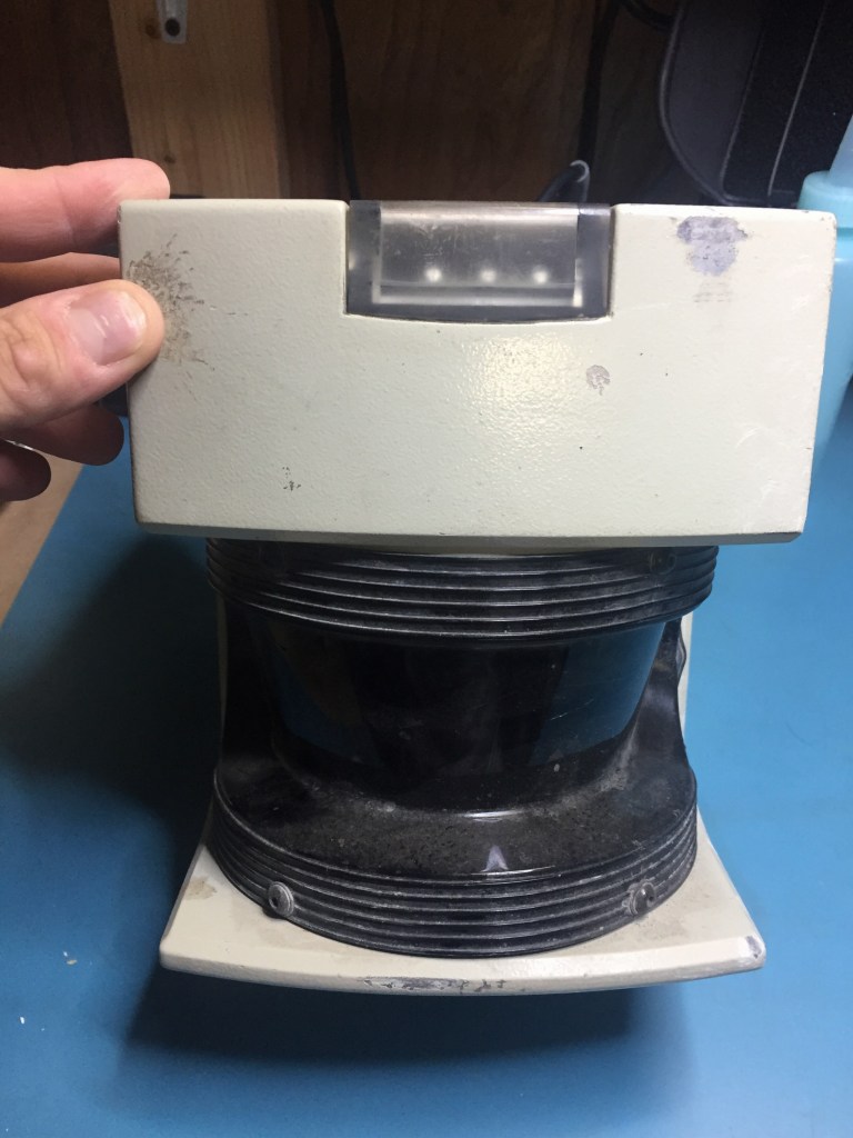
The sensor feels solid and feels like a brick. I could probably throw it off a cliff and it will still work, not that you should try…
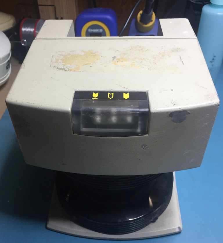
SICK LMS 291. You can see the front black area where the laser shoots out from. The 3 indicator lights at the top front, and the cutout in the back for the connectors.
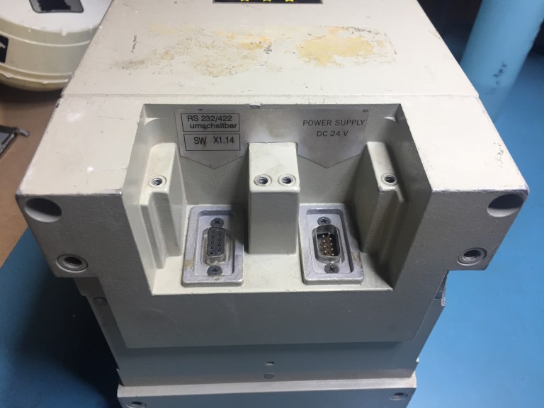
SICK LMS 291 power and serial communications ports. There is a large sealed connector that plugs into each slot.
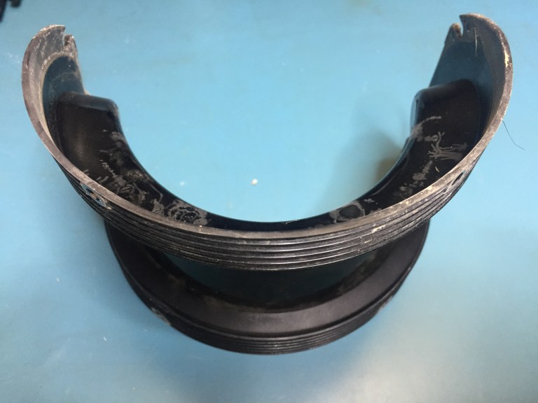
Front Plastic Shield
Mirror and encoder wheel. The laser shoots down from above the spinning mirror. The green post on the left reads the position from the encoder wheel shown on the bottom. The encoder wheel is the metal wheel with the slots cut into it. The 6 black tubes on the bottom I think are IR LEDs that are used for detecting dust or anything else occluding the front black visor.
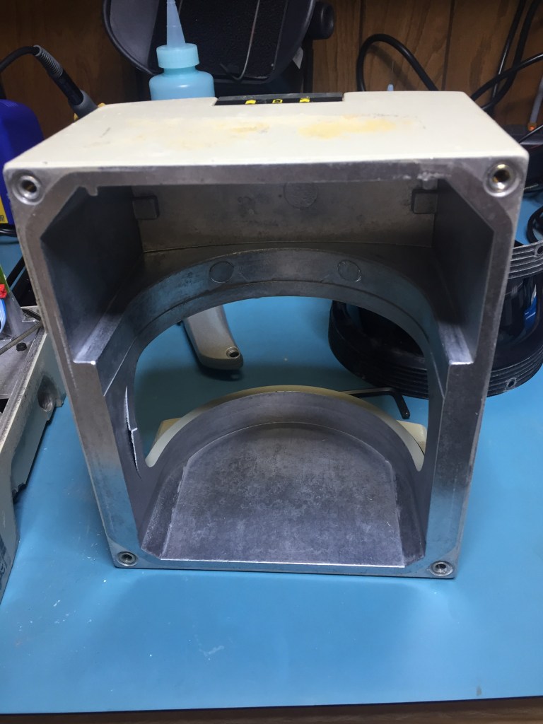
Front Metal Case removed. Walls are about 3/10″ or 7.6mm thick
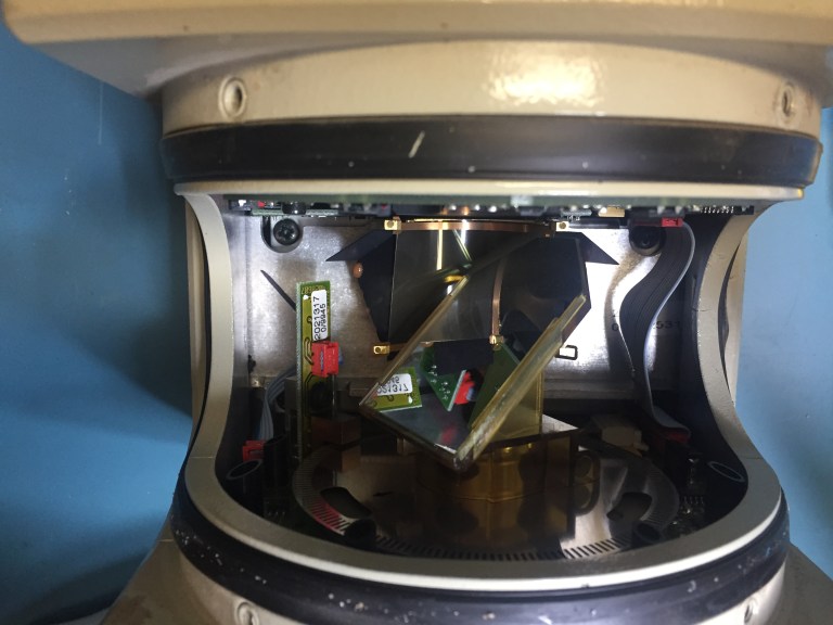
With the front removed here are the internals of the sensor. On the bottom you can see the metal ring which is a motor, above it is the spinning mirror encoder. The top section has the control boards and the laser hidden behind them.
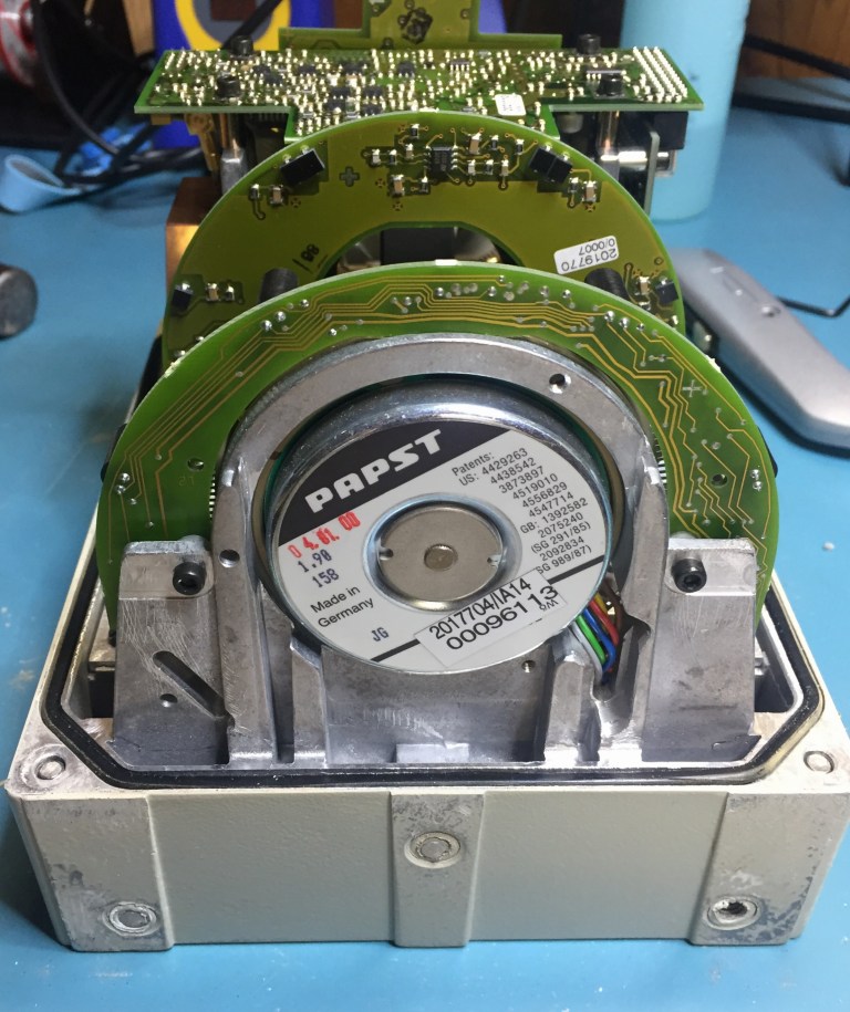
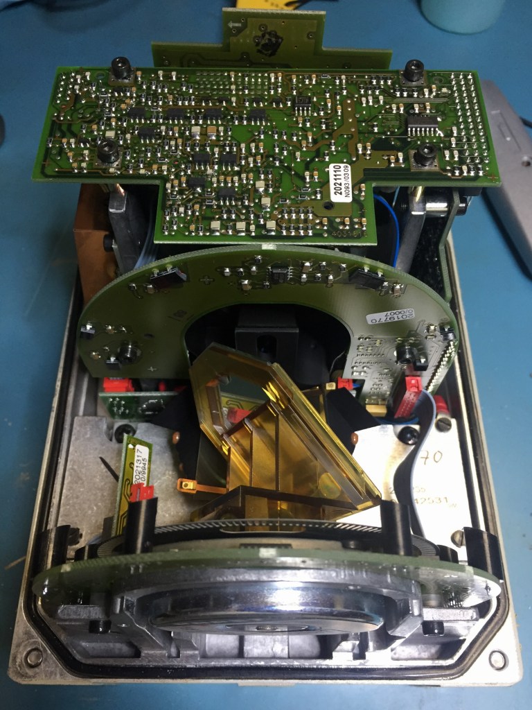
Bottom view of the open sensor. The motor for spinning the mirror and encoder wheel is clearly visible at the bottom. The black rectangles on the top board are for detecting if the bottom LEDs are visible for fault detection.
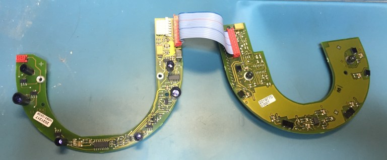
These are the wings that go below and above the spinning mirror assembly. On the left side you can see the LEDs and the board on the right has the black square receivers.
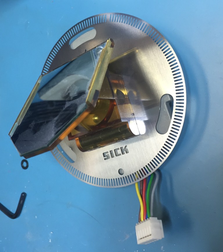
The encoder is directly mounted to the mirror for increased accuracy of the laser position. It is very solidly built, and you can see that a designer was having fun with cutting the SICK logo into the metal disk. I was surprised when I saw this since I expected a higher resolution encoder wheel with more slots. But I guess the larger thicker slots can be more reliable. Towards the top of the wheel it looks like one slot is missing, I wonder if it is some sort of index.
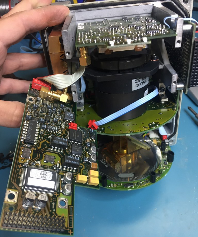
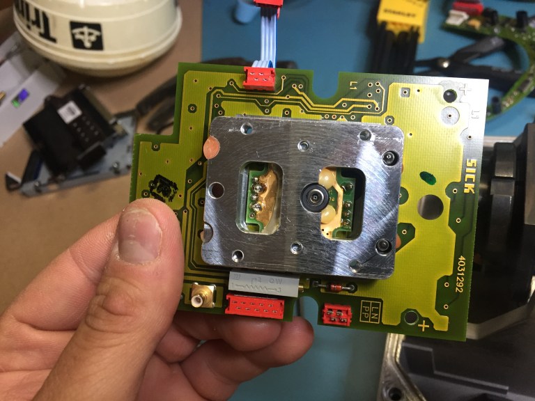
Laser and receiver black can assembly visible after removing the front PCB. You can see the 2 gold coax connectors probably for some high frequency signals from the receiver. On the top board in the front you can see the 3 indicator lights that are visible on the exterior of the enclosure. On the left of the front board you can see the board interconnect connector that connects to the board on the right side of this image. When the boards are screwed down that connector is not coming loose.
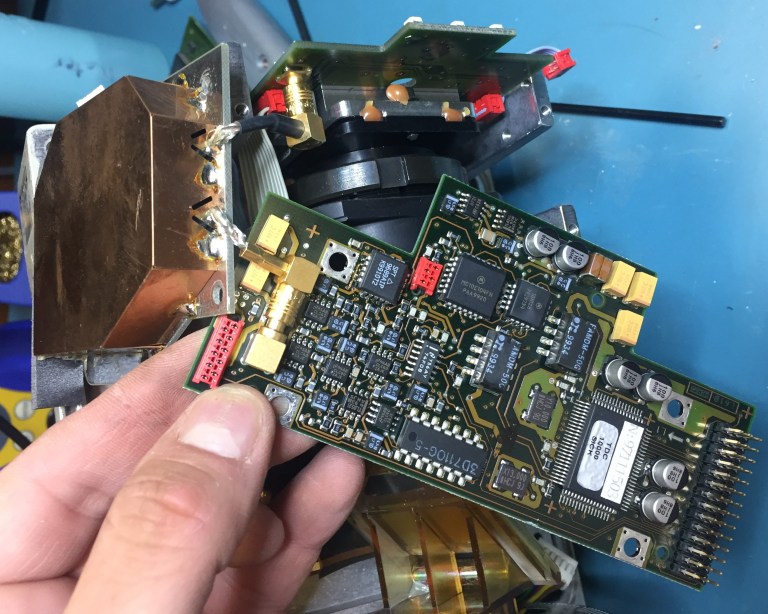
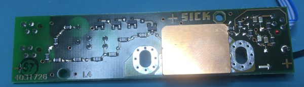
Front board that I think converts the analog RF receiver signal to digital for the processor board. The board on top has the reciever, a coax cable goes from there to the gold can. Followed by going to this board. I am really curious what is under the gold can.
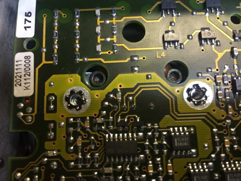
Look at the washers used above the screw holes. Excellent attention to detail to avoid screws coming loose from vibration. Not shown but there are many really nice touches, such as captive standoffs. I was surprised that I did not see any loctite.
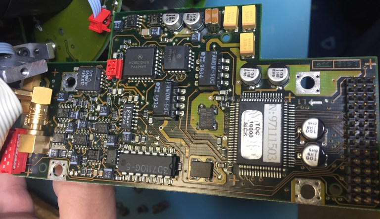
Close up of the front board. Perhaps some RF signal conditioning for the receiver of the laser signal.
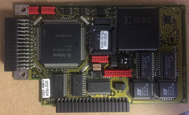
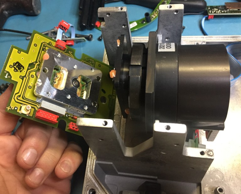
The main processor board that was connected to the front board shown before from the left side board connector. You can see the Xilinx FPGA that is running the sensor.
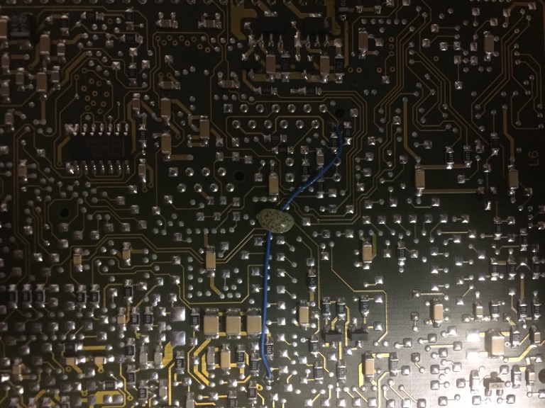
Bodge wire on the rear of the main processing board. I am surprised to see this. However it is really well done. Look at the epoxy blob holding the wire down.
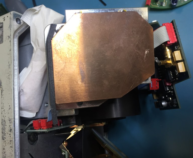
Metal gold can to shield some components (or so I thought) from EM interference. Desiccant packet on the left is to control any moisture that might get into the sensor.
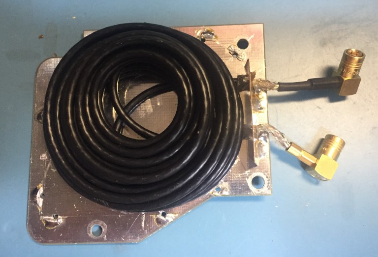
Inside of the shielding can. Is that for creating a time delay or some phase shift in the RF signal coming from the receiver?
Receiver of the incoming laser signal on the top board center. The black can has some mirrors and the laser.
Laser receiver module closeup. What is all the metal heatsinking for?
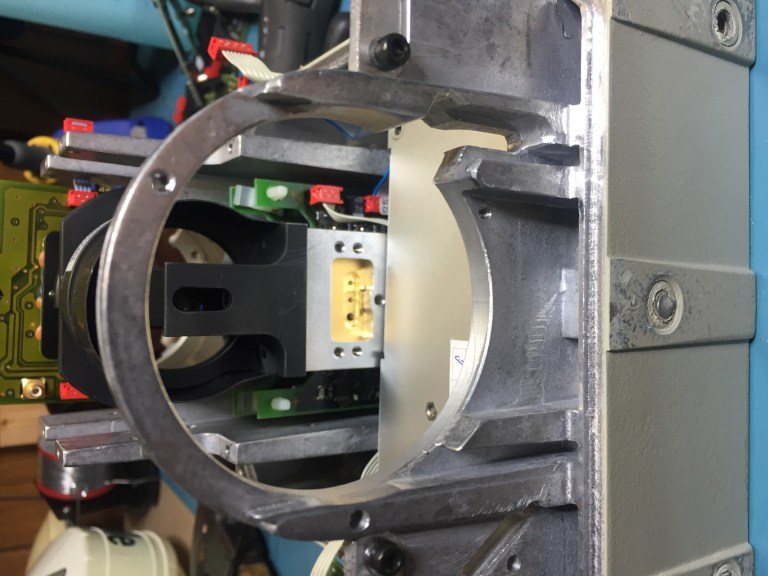
The motor and mirror removed. You can sort of look up into the laser and reciever assembly. The flat metal part between the ring and the laser assembly is the back of the power supply module.
Looking up from the mirror into the laser assembly. Most of the center that you see is a mirror. The slot in the plastic has its own mirror that points the laser from the gold block down to the spinning mirror. The returned signal goes on the sides of that slot to the receiver above.
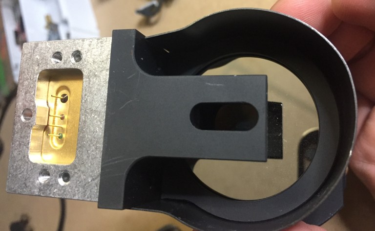
Laser that is connected to the slot in the black mirror can.
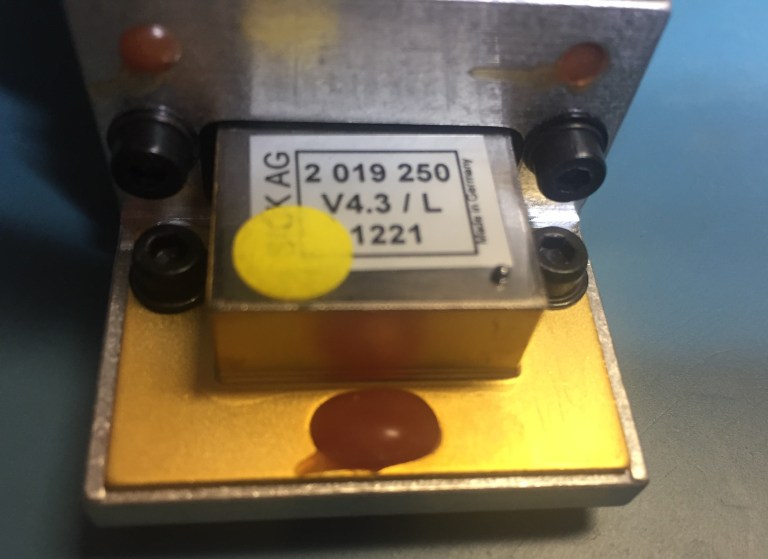
Connected to gold pins above to (control) the laser. What is under that shield??
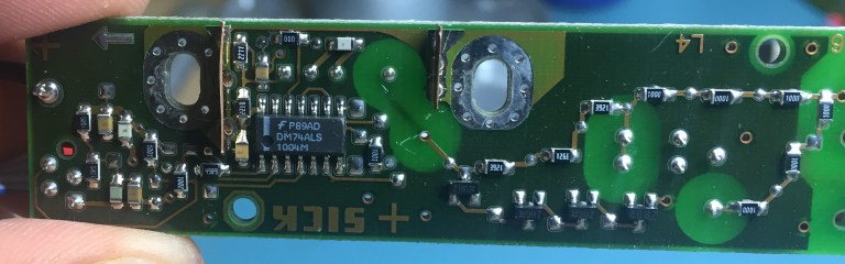
Under the shield. The DM74ALS seems to be a quad 2 input nand gate.
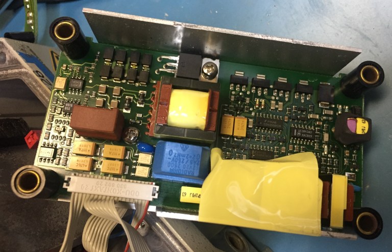
The power supply for the sensor that was located behind the spinning mirror module.
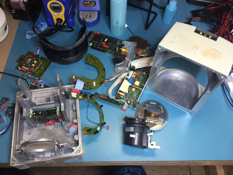
All of the components in the LIDAR sensor. The PCB that is still in the rear metal enclosure is the board that connects to the power and serial connectors that we saw on the external of the sensor before.
I hope you enjoyed seeing the internals of this sensor. It is interesting to see how they made it and the spinning mirror that we often hear about. Leave comments below to help identify parts or other questions you may have.
tags: c-Education-DIY, Infographics, LIDAR, Robotics technology, Sensing

AUAI is supported by: