
Robohub.org
Robotics, maths, python: A fledgling computer scientist’s guide to inverse kinematics
 So – you’ve built a robot arm. Now you’ve got to figure out how to control the thing. This was the situation I found myself in a few months ago, during my Masters project, and it’s a problem common to any robotic application: you want to put the end (specifically, the “end effector”) of your robot arm in a certain place, and to do that you have to figure out a valid pose for the arm which achieves that. This problem is called inverse kinematics (IK), and it’s one of the key problems in robotics.
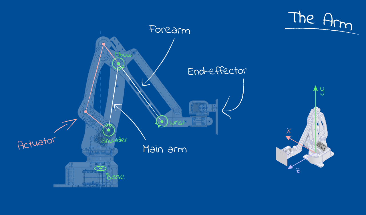
The Arm
The design I used is based on industrial pallet-packing robots, and at its core has three degrees of freedom, or ‘axes’ on which it can move. Think left to right, in and out and up and down; it basically means that the arm can move in three different ways. The GIFs below show the different types of movement: the entire arm can swivel on its base, the “main arm” translates the elbow in and out from the centre, and the “actuator” drives the forearm, which in turn translates the end-effector up and down. A 3-DOF arm like this has the handy property of having a unique solution for each possible position of its end-effector, which made the IK task approachable to someone like me, who’s never done this type of thing before.
Swing

Main
Actuator
Like many well-studied problems, IK has generic solutions, but these are numerically-based and computationally complex. I wanted a simple and efficient solution, so I decided to approach the control of my arm analytically, using geometric principals and logic. The result of this work was a graphical Python application, which connected to the arm via serial and allowed the user to move the goal position of the end-effector by clicking and dragging, or by sending commands from another application running on the same computer (this IK application made up a key part of my project, but that’s a topic for another time).
Here’s a quick look at what I ended up with:
Heads up: The code in this post is written in Python with Numpy, and there’s maths. I won’t pretend that any of the ideas presented here are optimal (or good, for that matter), but hopefully you’ll be able to scrounge something useful!
Let’s go already
To start with, let’s consider the “swing” action of the arm, as it rotates on its base. Since the main arm, elbow and forearm are all constrained to a single plane (look at the GIFs above: only the swing rotation affects the left-right position of the wrist), all we really have to do here is line up that plane – a line from our top-down perspective – with the goal point, ignoring the goal’s vertical position. If this sounds easy, you’re right: it’s plain old trigonometry. Unfortunately for me, a quirk of my design left the arm’s operation plane just off-centre of the axis of rotation, which made the solution much less obvious.
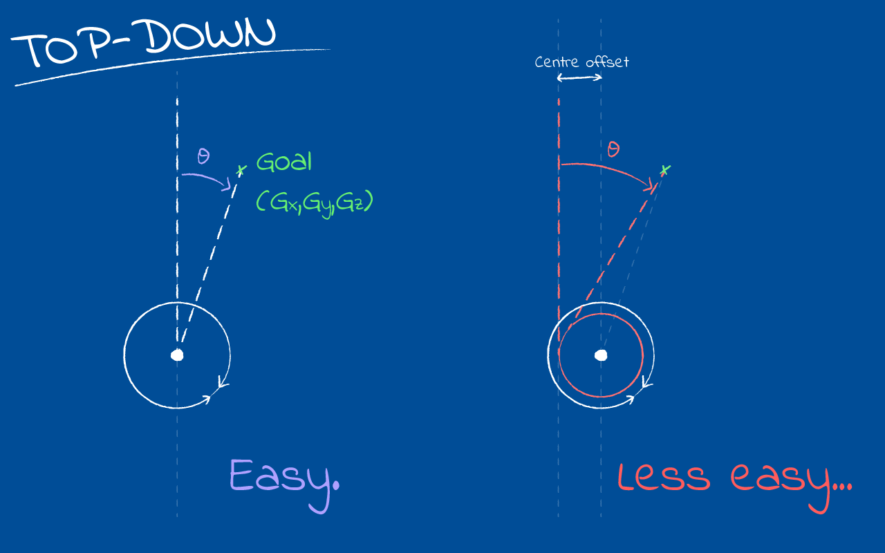
Using the naive trigonometric approach here results in pointing off to the left of the actual goal (right if the shoulder sits on the other side), and the gap is big enough that this is a real problem. I took a shot at solving this geometrically, but quickly decided it wasn’t worth my time figuring it out. In the end, I resorted to an extremely simple numerical technique called a binary search. I’ve used this in the past for other tough geometric problems, like finding an intersection between a Bezier curve and a circle.
In a binary search (also known as the “Bisection Method”), you essentially come up with arbitrary upper and lower bounds for your variable – in this case, theta – and then examine the midpoint to find whether it’s larger or smaller than your target. If it’s larger, then the midpoint becomes your new upper bound; if it’s smaller, the midpoint is your new lower bound. Repeat until you’ve bounded your variable with sufficient accuracy. A binary search is conceptually simple and computationally cheap, and converges fairly quickly: you halve your search space each iteration. I found 3-5 iterations got me within 0.3 degrees of the true value, well within the limits of what my servo motors could practically target.
On to the solution! What we’re actually searching for is the point at which the vector representing our arm is lined up with the vector from the arm’s shoulder joint to the goal: where the angle between these two vectors is zero. Normally, when taking the angle between two vectors (call them A and B) you get the absolute angle out, with no directionality. However, with this search method it’s important to have a signed distinction between “too high” and “too low”. To get around this, I wrote a simple function to find a signed angle between two vectors, with negative showing that A points counter-clockwise to B, and positive showing that A points clockwise from B:
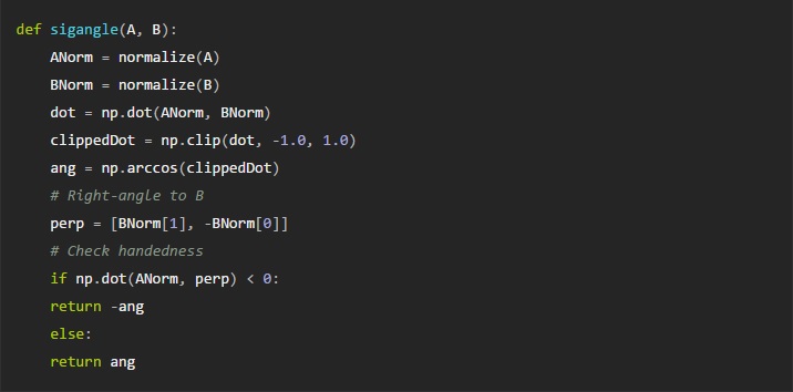 This works by taking a perpendicular vector from B (pointing clockwise), and dot-ing it with A to see how much they line up (using the dot product for
vector projection).
If A points clockwise of B then np.dot(A, perp) will be positive, and vice-versa.
Note that the normalize() function simply sets a vector’s length to 1, while keeping it pointed in the same direction. Mathematically, it’s just doing: A=|A|-1 (np.clip() just keeps the dot product between 1 and -1).
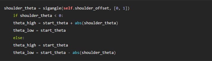
With that, we can now perform our binary search and find a decent approximation to the target angle. We need a reasonable starting point, so let’s just use the angle from the origin to the goal (the naive approach I mentioned above). Numpy provides a very useful function for finding the angle np.arctan2(y, x) which resolves the arc-tangent of in the correct quadrant.
Now, it’s important to check which side the shoulder sits on: this lets us decide whether to use start_theta as an upper or lower bound. This is as simple as testing the signed angle between the shoulder offset vector (from the origin) and a vector pointing straight forwards. At the same time, we can also establish the other bound by taking the absolute value of this angle and adding or subtracting it from start_theta, since this angle to the shoulder is always going to be greater than the error of start_theta.
With our initial bounds established, the actual search loop is pretty straightforward. Note the use of an iteration counter: it’s only there in case something goes wrong (e.g. if we input an unsolvable configuration), since in normal operation the loop exits once the desired accuracy is reached. We iteratively update self.swing, which will hold the new target swing angle at the end of the search.
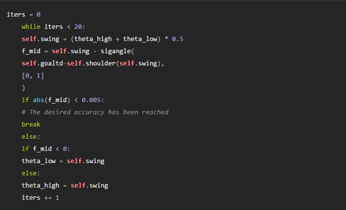
Note that the self.shoulder(angle) function just generates the top-down (x, z) position of the shoulder joint for a given swing angle. Besides the swing angle, there’s one other important result from this stage of IK: the radial distance, from the shoulder joint to the end-effector. The calculation is simple enough:
goal_radial = np.linalg.norm(self.goaltd – self.shoulder(self.swing))
Round in circles
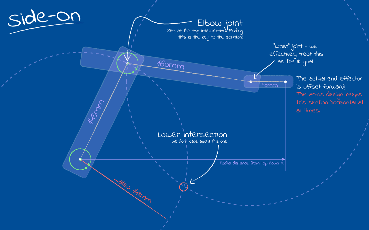
We know which way to point: now, let’s consider the movement of the arm in its ‘plane of operation’, which covers the goal end-effector position and the line extending vertically (+y) from the shoulder joint. The main arm and forearm both move across this plane. The trick here is that we’ll still be using a 2D coordinate system, basically a local frame of reference, where our y value remains the same but the x value is the radial distance of the point we’re interested in. For the goal, we computed this radial distance above in the top-down IK, so we can go ahead and construct goalpl – the ‘planar’ goal – which lies at: goalpl=(goal_radial/goaly).
Side-on, the main arm and forearm form an upright triangle between the shoulder joint and goalpl with the elbow joint sitting at the peak. It’s important to note that the arm’s sections are different lengths, with the forearm being a bit longer. Now, in this plane we’re solving given the end effector’s position, and the origin is static. That just leaves the position of the elbow joint to solve for, which we can do geometrically, since it’s at a fixed distance from both the origin and effector. If we draw two circles, one fixed about the origin with radius = main arm length, and one centred on the end-effector with radius = forearm length, then the elbow must be at one of the two possible intersections between these circles:
 Let’s look at a simple Python class which deals with this intersection calculation. There’s a few possible cases for circle-circle intersection, most of which invalidate our solver: if the circles do not contact, either by being separated or in the case that one contains another, then there is no valid solution; if the circles are coincident (impossible for this design, since the radii differ) then there are infinite possible solutions; however, when the circle borders intersect, we can find two distinct intersection points.
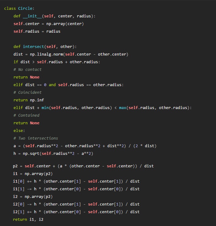
For any case we’re interested in, it’s the top intersection that matters. This means we can just pick the one with the largest y value, and call it a day:
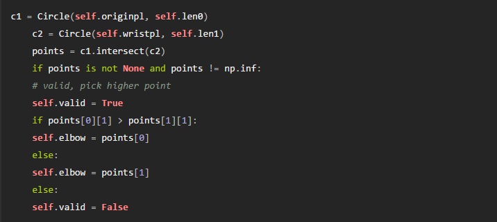
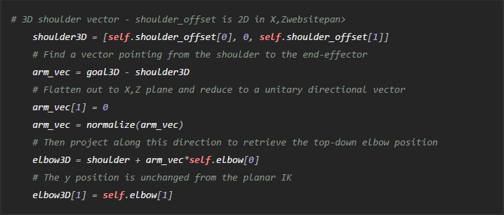
And – that’s it! We have the swing angle, and a valid position for the elbow joint to match the shoulder and goal end-effector positions. That’s all we need to define a valid pose for the arm. If you need to, you can reconstruct the positions in 3D space:
Wrapping up
If you’ve made it this far, I hope you’ve found this interesting and/or enlightening. Want to see how it all fits together? I’ll be uploading the full IK application to GitHub here, along with all the design files for the robotic arm. If you’re feeling ambitious, you should be able to 3D-print and build your own to play around with 
Other notes:
- I didn’t design the arm completely from scratch: check out the original “LiteArm” design on Thingiverse.
- The IK application uses PyGame, a no-frills SDL wrapper for Python, to open and draw to the graphical window. I’ll probably switch to a meatier library for further development, but this did the job of basic “drawn-to-screen” stuff nicely.
Written by Alistair Wick for the University of Bristol Engineering Maths blog. The original post, and future follow-ups, are available on Alistair’s website.
If you liked this article, you may also enjoy these:
- TrotBot tackles rough terrain
- Sticky business: Five adhesives tested for 3D printing
- Meet RoboGabby: She’s on a mission to teach more girls about robotics
- Adjust how you learn and quickly pick up robotics programming
- 3-D printing hydraulically-powered robots, no assembly required
See all the latest robotics news on Robohub, or sign up for our weekly newsletter.
tags: Actuation, Algorithm Controls, c-Education-DIY, coding, cx-Research-Innovation, education, Manipulation

AUAI is supported by: