
Robohub.org
Robots 101: Lasers
By Ilia Baranov
In this new Robots 101 series, we will be taking a look at how robots work, what makes designing them challenging, and how engineers at Clearpath Robotics tackle these problems. To successfully operate in the real world, robots need to be able to see obstacles around them, and locate themselves. Humans do this mostly through sight, whereas robots can use any number of sensors. Today we will be looking at lasers, and how they contribute to robotic systems.
 Overview
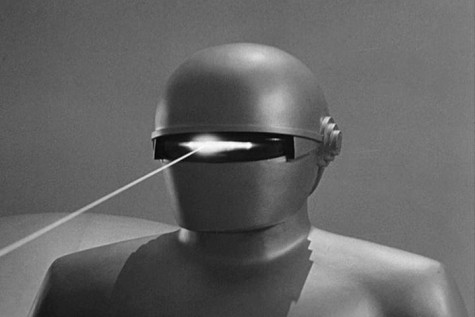
When you think of robots and lasers, the first image that comes to mind might come from science fiction; robots using laser weapons. However, almost all robots today use lasers for remote sensing. This means that the robot is able to tell, from a distance, some characteristics of an object. This can include size, reflective, color, etc. When the laser is used to measure distance in an arc around the robot, it is called LIDAR. LIDAR is a portmanteau of Light and Radar, essentially think of a sweeping radar beam shown in the films, using light.
Function and Concepts
By Mike1024, via Wikimedia Commons
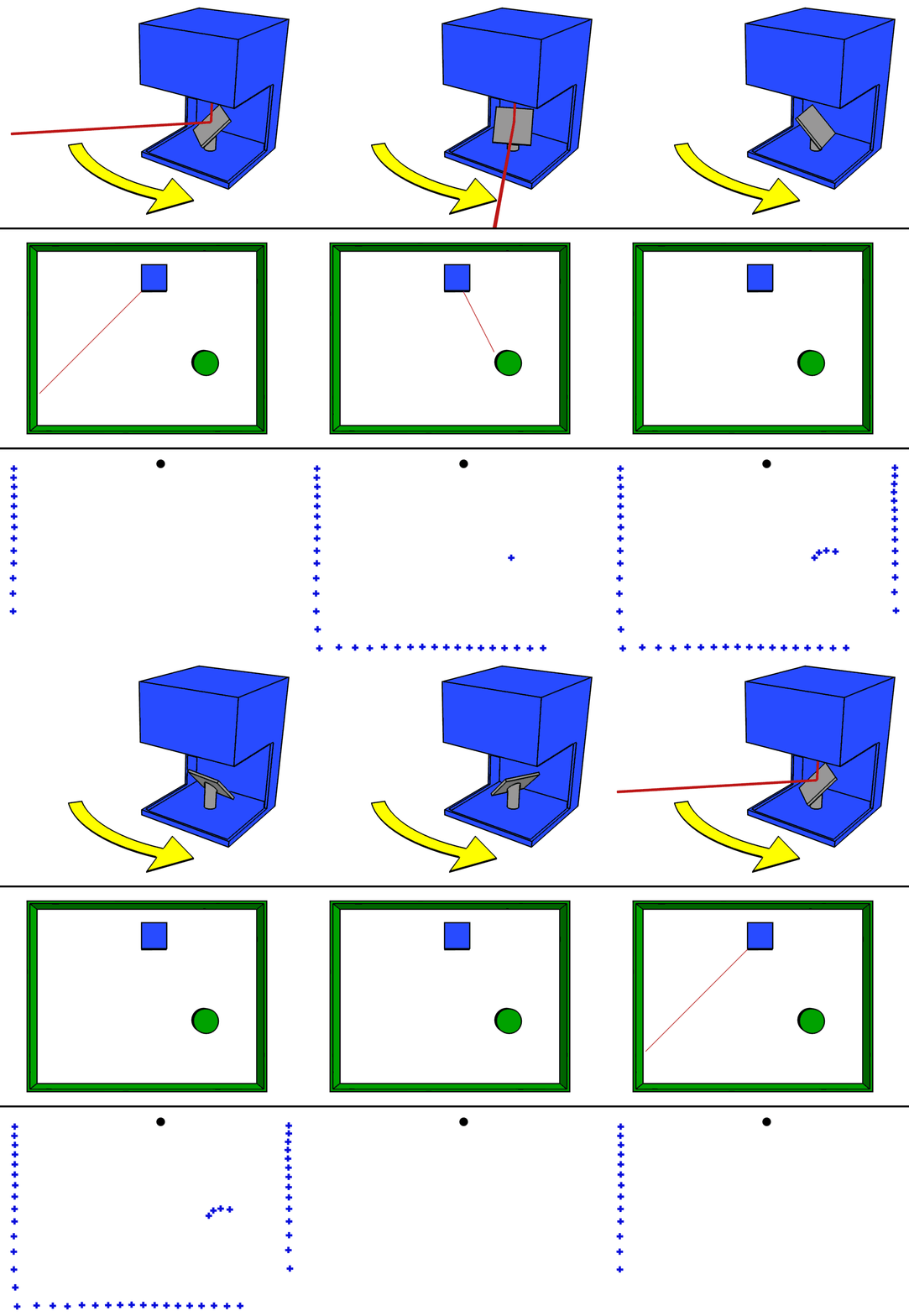
All LIDAR units operate using this basic set of steps:
1. Laser light is emitted from the unit (usually infrared)
2. Laser light hits an object and is scattered
3. Some of the light makes it back to the emitter
4. The emitter measures the distance (more on how later)
5. Emitter turns, and process begins again
A great visual deception of that process to the right.
Types of LIDAR sensing
How exactly the laser sensor measures the distance to an object depends on how accurate the data needs to be. Three different methods commonly found on LIDAR sensors are:
Time of flight
The laser is emitted, and then received. The time difference is measured, and distance is simply (speed of light) x (time). This approach is very accurate, but also expensive due to the extremely high precision clocks needed on the sensor. Thus, it is usually only used on larger systems, and at longer ranges. Rare to use on robots
Phase difference
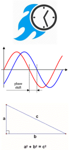
In this method, the emitted laser beam is modulated to a specific frequency. By comparing the phase shift of the returned signal on a few different frequencies, the distance is calculated. This is the most common way laser measurement is done. However, it tends to have limited range, and is less accurate than time of flight. Almost all of our robots use this.
 Angle of incidence
The cheapest and easiest way to do laser range-finding is by angle of incidence. Essentially, by knowing what angle the reflected laser light hits the sensor, we can estimate the distance. However, this method tends to be of low quality. The Neato line of robotic vacuum cleaners use this technology.
Another thing to note is that so far, we have only discussed 2D LIDAR sensors. This means they are able to see a planar slice of the world around them, but not above or below. This has limitations, as the robot is then unable to see obstacles lower or higher than that 2d plane. To fix this issue, either multiple laser sensors can be used, or the laser sensor can be rotated or “nodded” up and down to take multiple scans. The first solution is what the Velodyne line of 3D LIDAR sensors employ, while the second solution tends to be a hack done by roboticists. The issue with nodding a LIDAR unit is a drastic reduction of refresh rate, from tens of Hz, down to 1 Hz or less.
Manufacturers and Uses
Some of the manufacturers we tend to use are SICK, Hokuyo, and Velodyne.
This is by no means an exhaustive list, just the ones we use most often.
SICK
Most of our LIDARs are made by SICK. Good combo of price, size, rugged build, and software support. Based in Germany
Hokuyo
Generally considered cheaper than SICK, in larger quantities. Some issues with fragility, and software support is not great. Based in Japan
Velodyne
Most expensive, used only when robot MUST see everything in the environment. Based in US.
Once the data is collected, it can be used for a variety of reasons. For robots, these tend to be:
- Mapping
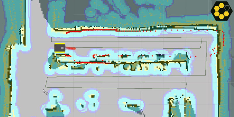
- Use the laser data to find out dimensions and locations of obstacles and rooms. This allows the robot to find its position (localisation) and also report dimensions of objects. The title image of this article shows the Clearpath Robotics Jackal mapping a room.
- Survey
- Similar to mapping, however this tends to be outside. The robot collects long range data on geological formations, lakes, etc. This data can then be used to create accurate maps, or plan out mining operations.
- Obstacle Avoidance
- Once an area is mapped, the robot can navigate autonomously around it. However, obstacles that were not mapped (for example, squishy, movable humans) need to be avoided.
- Safety Sensors
- In cases where the robot is very fast or heavy, the sensors can be configured to automatically cut out motor power if the robot gets too close to people. Usually, this is a completely hardware-based feature.
Selection Criteria
A lot of criteria is used to select the best sensor for a given application. The saying goes that an engineer is someone who can do for $1 what any fool can do for $2. Selecting the right sensor for the job not only reduces cost, but also ensures that the robot has the most flexible and useful data collection system.
- Range
- How far can laser sensor see? This impacts how fast a robot is able to move, and how well it is able to plan.
- Light Sensitivity
- Can the laser work properly outdoors in full sunlight? Can it work with other lasers shining at it?
- Angular Resolution
- What is the resolution of the sensor? More angular resolution means more chances of seeing small objects.
- Field of view
- What is the field of view? A greater field of view provides more data.
- Refresh rate
- How long does it take the sensor to return to the same point? The faster the sensor is, the faster the robot can safely move.
- Accuracy
- How much noise is in the readings? How much does it change due to different materials?
- Size
- Physical dimensions, but also mounting hardware, connectors, etc
- Cost
- What fits the budget?
- Communication
- USB? Ethernet? Proprietary communication?
- Power
- What voltage and current is needed to make it work?
- Mechanical (strength, IP rating)
- Where is the sensor going to work? Outdoors? In a machine shop?
- Safety
- E-stops
- regulation requirements
- software vs. hardware safety
For example, here is a collected spec sheet of the SICK TIM551.
| Range (m) | 0.05 – 10 (8 with reflectivity below 10%) |
| Field of View (degrees) | 270 |
| Angular Resolution (degrees) | 1 |
| Scanning Speed (Hz) | 15 |
| Range Accuracy (mm) | ±60 |
| Spot Diameter (mm) | 220 at 10m |
| Wavelength (nm) | 850 |
| Voltage (V) | 10 – 28 |
| Power (W) (nominal/max) | 3 |
| Weight (lb/kg) | 0.55/0.25 |
| Durability (poor) 1 – 5 (great) | 4 (It is IP67, metal casing) |
| Output Interface | Ethernet, USB (non-IP67) |
| Cost (USD) | ~2,000 |
| Light sensitivity | This sensor can only be used indoors. |
| Other | Can synchronize for multiple sensors.Connector mount rotates nicely. |
If you liked this article, you may also be interested in:
- ROS 101: Intro to the Robot Operating System
- ROS 101: A practical example
- Arduino for Makers #1: Setting up a development station
- Arduino for Makers #2: Deconstructing Arduino programs
- Robots Podcast: Soft Robotics Toolkit, with Donal Holland
See all the latest robotics news on Robohub, or sign up for our weekly newsletter.
tags: c-Education-DIY, LIDAR, tutorial, Vision
