Robohub.org
The Monospinner: world’s mechanically simplest controllable flying machine
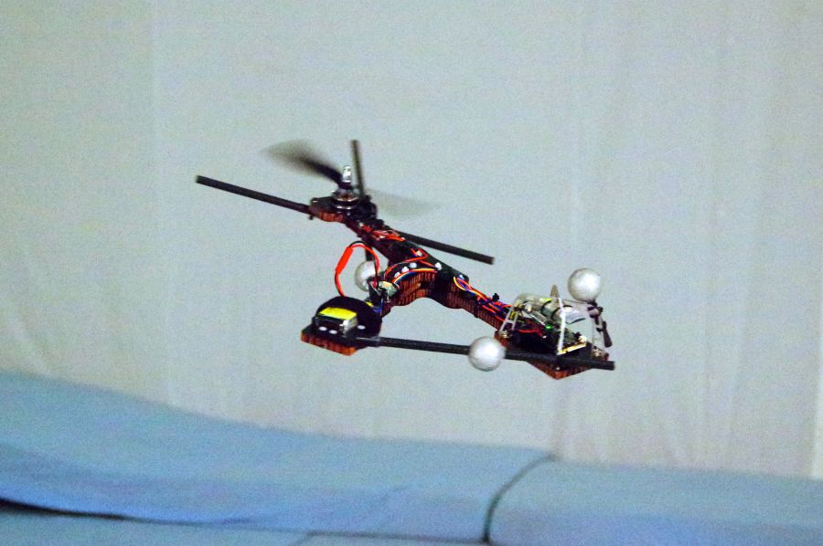
Fig. 1. The Monospinner in flight.
The Monospinner (Fig.1), developed at the Institute for Dynamic Systems and Control at ETH Zurich, is the mechanically simplest, controllable, flying machine in existence. It has only one moving part (the rotating propeller), but can still fully control its position in space. The vehicle features no additional actuators or aerodynamic surfaces.
Our research group aims at pushing the boundaries of flying machines by asking fundamental questions, such as “what is the minimum number of moving parts necessary for controlled flight?” All common flying vehicles require multiple moving parts: conventional quadrocopters, for example, have four moving parts (the four fixed-pitch propellers). A helicopter’s main rotor requires a complicated swashplate mechanism with many moving parts, and a typical fixed-wing airplane requires one moving part for each of the ailerons, rudder, elevator, and main propulsion. Samara-type vehicles look like maple seeds (or samaras), and rotate while flying. These vehicles typically need two actuators to be controllable in position. Some toys have only one moving part, but are not controllable in the horizontal direction.
We set out to create a vehicle that has only a single moving part. The theoretical basis for this followed from previous work on quadrocopters, where we showed that a quadrocopter can maintain flight despite the complete loss of one, two, or three propellers. To do this, we redefined the definition of “to hover”: now the vehicle may rotate at a constant angular velocity as long as it remains approximately at the same point in space. Of course, the vehicle then has to be controlled near this hover solution, to allow it to track trajectories and reject disturbances.
This is tricky for the Monospinner, as it has only a single input (the thrust force) to control its states (compared to a conventional quadrocopter that has four inputs). We designed a cascaded controller (Fig. 2): the faster inner loop controls the thrust direction, while the slower outer loop controls the vehicle’s acceleration and thereby position. Roughly speaking, the single control input (the thrust magnitude) is decomposed into two parts, the average part of the thrust (calculated by the outer loop) which determines the acceleration of the Monospinner and the deviation from the average thrust (calculated from the inner loop) which controls its orientation.
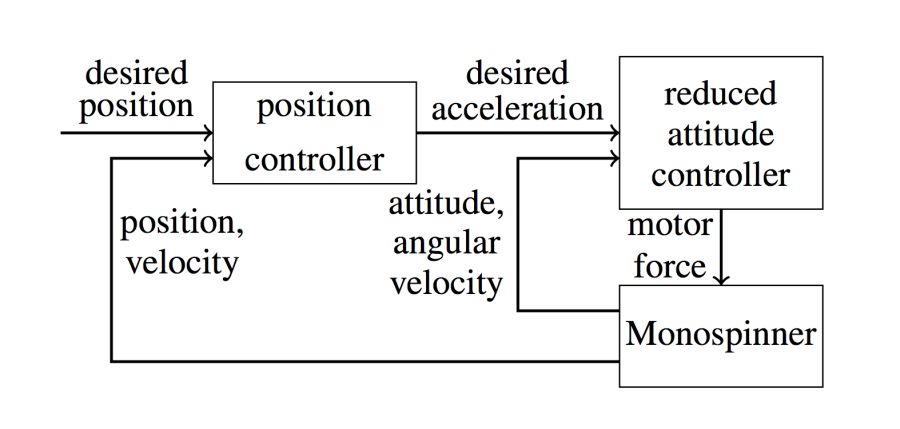
Fig. 2. Cascaded control structure: the outer position controller defines a desired acceleration, where the inner attitude controller defines the vehicle’s attitude.
After the theoretical analysis, we proceeded to build a vehicle. However, there are a lot of uncertainties in the real world: one example is that we do not have a good aerodynamic model of such a complex rotating object. In addition, there are uncertainties such as the mass distribution or the position of the vehicle’s center of mass. We set out to design something that would fly even if we did not know the parameters exactly. We evaluated different designs using Monte Carlo simulations, where we sample different perturbations from the above-mentioned uncertainties and use simulations to test whether our controller would still work. We did this until we found a configuration that works in most situations: the resulting Y-shaped vehicle is shown in Fig. 3 below.
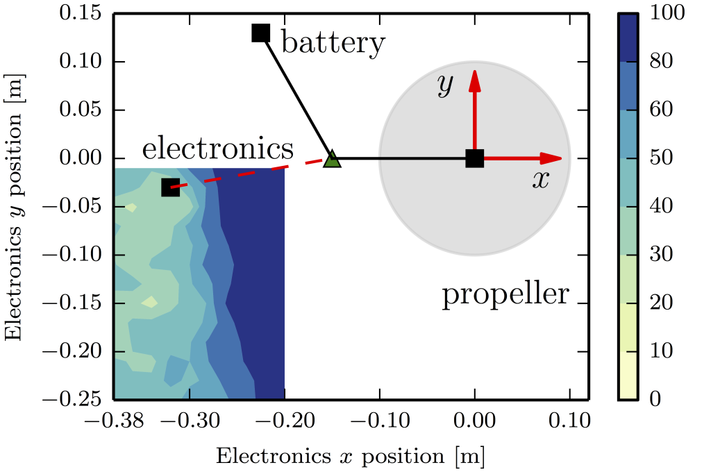
Fig. 3. Monte Carlo simulation results, showing how likely a vehicle is to be controllable (the color scale indicates the likelihood of a crash) as a function of where the vehicle’s electronics are placed. The vehicle’s approximate size and shape are based on existing vehicles.* The vehicle has three main components, which are approximately equally massive: the battery, electronics, and the motor/propeller. By fixing the positions of the propeller and the battery as two vertices of an equilateral triangle, a Monte Carlo analysis was conducted for different positions of the electronics in the vicinity of the third triangle vertex. The final electronics position was chosen as a compromise between low likelihood of failure (as determined by the Monte Carlo simulations) and other considerations (such as ease of mechanical construction). This location is plotted with a red dashed line.
The control strategy only works near hover, where the vehicle spins about 4 revolutions per second. To get the vehicle near the operating angular velocity, we built a passive platform (Fig. 4 below), which has a vertically oriented bearing allowing the Monospinner to rotate freely. The rotation is achieved through the reaction torque of the propeller, and the thrust is slowly ramped up from zero. Once the vehicle is sufficiently near the hover angular velocity, the controller is switched on and the vehicle jumps off the platform. The platform ensures that the take-off condition is near the hover solution for each experiment. Once we were confident that the vehicle would reliably work from such a controlled starting point, we pushed our luck, and we found out that the system is robust enough to recover after it is thrown into the air like a Frisbee (see the video).
There are still open questions, which we will explore in future work: for example, we plan to refine the control strategy to allow the Monospinnner to recover from a larger range of initial conditions.
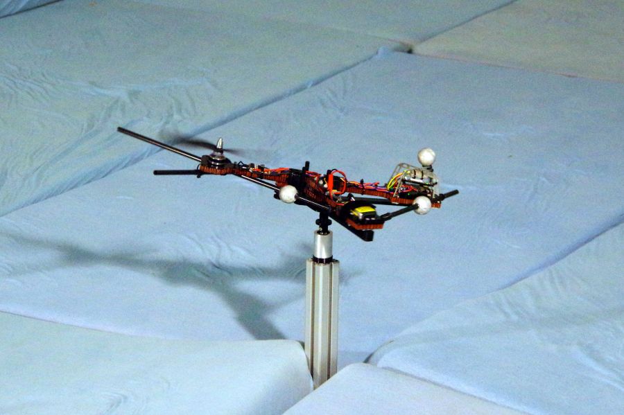
Fig. 4. The Monospinner resting on the takeoff platform, which allows the vehicle to freely rotate about its axis of rotation, so that the vehicle can take off near its hover angular velocity and orientation. We have since shown that the Monospinner can also be hand-launched, by throwing it like a Frisbee.
If you liked this article, you may also be interested in:
- Three new quadrotor videos demonstrate agile control and the power of machine learning
- Raffaello D’Andrea at TED2016: Novel flying machines and swarms of tiny flying robots
- Behind the scenes at TED Global: Raffaello D’Andrea and team demo amazing quadrotor “athletes”
- Quadrocopters learn from prior experience to improve slalom flying
See all the latest robotics news on Robohub, or sign up for our weekly newsletter.
tags: c-Aerial, cx-Research-Innovation, ETH Zurich


AUAI is supported by: