
Robohub.org
UgCS photogrammetry technique for UAV land surveying missions
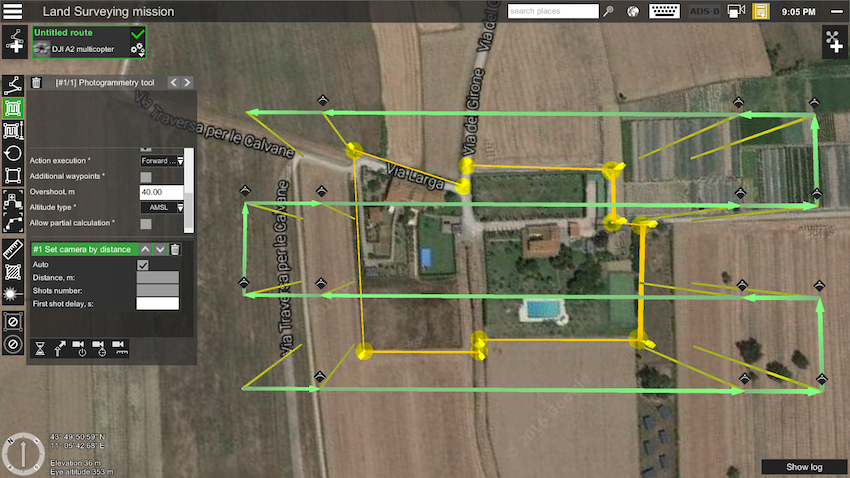
Figure 15: Adding 40m overshot to both ends of each survey line
UgCS is easy-to-use software for planning and flying UAV drone-survey missions. It supports almost any UAV platform, providing convenient tools for areal and linear surveys and enabling direct drone control. What’s more, UgCS enables professional land survey mission planning using photogrammetry techniques.
How to plan photogrammetry mission with UgCS
Standard land surveying photogrammetry mission planning with UgCS can be divided into following steps :
- Obtain input data
- Plan mission
- Deploy ground control points
- Fly mission
- Image geotagging
- Data processing
- Map import to UgCS (optional)
https://www.youtube.com/watch?v=SalCQoG6WUw&feature=youtu.be
Step one: Obtain input data
Firstly, to reach the desired result, input settings have to be defined:
- Required GSD (ground sampling distance – size of single pixel on ground),
- Survey area boundaries,
- Required forward and side overlap.
GSD and area boundaries are usually defined by the customer’s requirements for output material parameters, for example by scale and resolution of digital map. Overlap should be chosen according to specific conditions of surveying area and requirements of data processing software.
Each data processing software (e.g., Pix4D, Agisoft Photoscan, Dronedeploy, Acute 3d) has specific requirements for side and forward overlaps for different surfaces. To choose correct values, please refer to documentation of chosen software. In general, 75% forward and 60% side overlap will be a good choice. Overlapping should be increased for areas with small amount of visual cues, for example for deserts or forests.
Often, aerial photogrammetry beginners are excited about the option to produce digital maps with extremely high resolution (1-2cm/pixel), and to use very small GSD for mission planning. This is very bad practice. Small GSD will result in longer flight time, hundreds of photos for each acre, tens of hours of processing and heavy output files. GSD should be set according to the output requirements of the digital map.
Other limitations can occur. For example, GSD of 10cm/pixel is required, but designed to use a Sony A6000 camera. Based on mentioned GSD and camera’s parameters, the flight altitude would be set to 510 meters. In most countries, maximum allowed altitude of UAV’s (without special permission) is limited to 120m/400ft AGL (above ground). Taking into account the maximum allowed altitude, the maximum possible GSD in this case could be no more than 2.3cm.
Step two: Plan your mission
Mission planning consists of two stages:
- Initial planning,
- Route optimisation.
-Initial planning:
The first step is to set surveying area using UgCS Photogrammetry tool. Area can be set using visual cues on underlying map or using exact coordinates of edges. The result – survey area is marked with yellow boundaries (Figure 1).
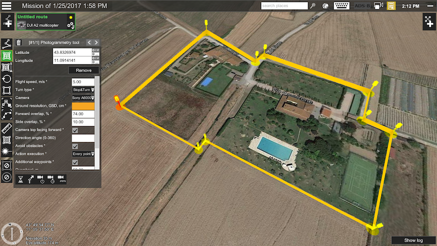
Figure 1: Setting the survey area
The next step is to set GSD and overlapping for the camera in Photogrammetry tool’s settings window (Figure 2).
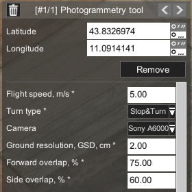
Figure 2: Setting camera’s Ground Sampling Distance and overlapping
To take photos in Photogrammetry tool’s setting window, define the control action of the camera (Figure 3). Set camera by distance triggering action with default values.
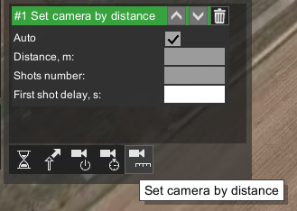
Figure 3: Setting camera’s control action
At this point, initial route planning is completed. UgCS will automatically calculate photogrammetry route (see Figure 4).
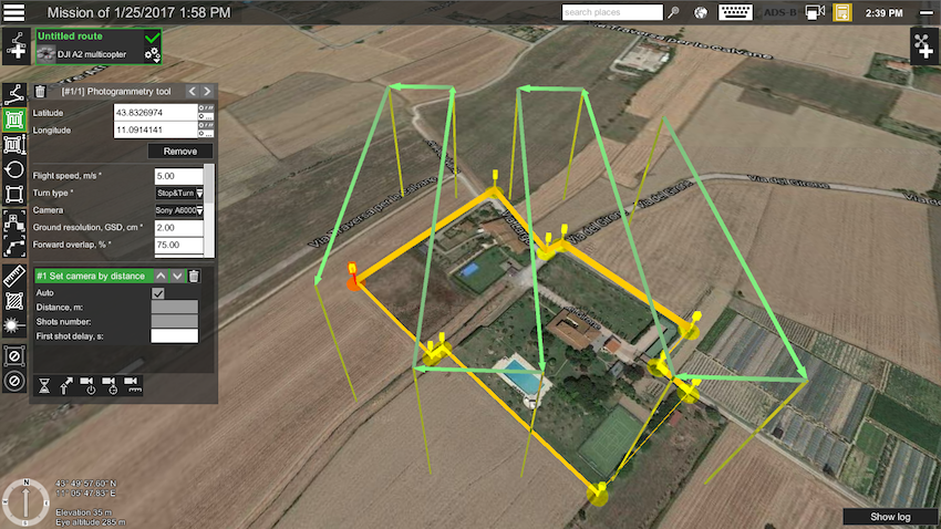
Figure 4: Calculated photogrammetry survey route before optimisation
-Route optimisation
To optimise the route, it’s calculated parameters should be known: altitude, estimated flight time, number of shots, etc.
Part of the route’s calculated information can be found in the elevation profile window. To access the elevation profile window (if it is not visible on screen) click the parameters icon on the route card (lower-right corner, see Figure 5), and from the drop-down menu select show elevation:
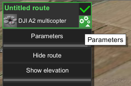
Figure 5: Accessing elevation window from Route cards Parameters settings
The elevation profile window will present an estimated route length, duration, waypoint count and min/max altitude data:
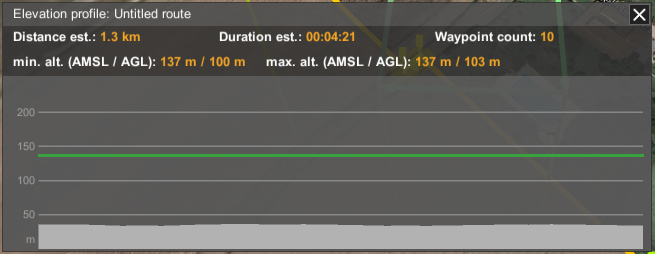
Figure 6: Route values in elevation profile window
To get other calculated values, open route log by clicking on route status indicator: the green check-mark (upper-right corner, see Figure 7) of the route card:
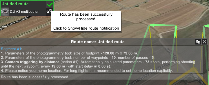
Figure 7: Route card and status indicator, Route log
Using route parameters, it can be optimised to be more efficient and safe.
-Survey line direction
By default, UgCS will trace survey lines from south to north. But, in most cases, it will be more optimal to fly parallel to the longest boundary line of the survey area. To change survey line direction, edit direction angle field in the photogrammetry tool. In the example, by changing angle to 135 degrees, the number of passes is reduced from five (Figure 4) to four (Figure 8) and route length is 1km instead of 1.3km.
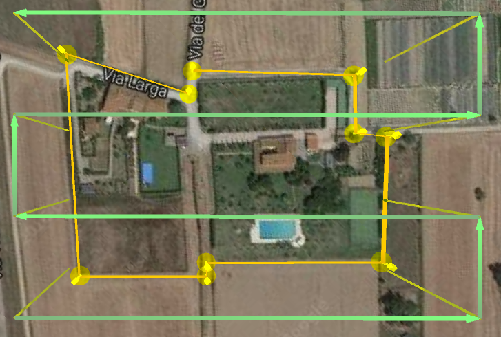
Figure 8: Changed survey line angle to be parallel to longest boundary
-Altitude type
UgCS Photogrammetry tool has the option to define how to trace the route according to altitude, with constant altitude above ground (AGL) or above mean sea level (AMSL). Please refer to your data processing software requirements as to which altitude tracking method it recommend.
In the UgCS team’s experience, the choice of altitude type depends on desired result. For orthophotomap (standard aerial land survey output format) it is better to choose AGL to ensure constant GSD for the entire map. If the aim is to produce DEM or 3D reconstruction, use AMSL so the data processing software has more data to correctly determine ground elevation by photos in order to provide more qualitative output.
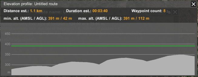
Figure 9: Elevation profile with constant altitude above mean sea level (AMSL)
In this case, UgCS will calculate flight altitude based on the lowest point of the survey area.
If AGL is selected in photogrammetry tool’s settings, UgCS will calculate the altitude for each waypoint. But in this case, terrain following will be rough if no “additional waypoints” are added (see Figure 10).
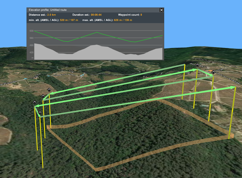
Figure 10: Elevation profile with AGL without additional waypoints
Therefore, if AGL is used, add some “additional waypoints” flags and UgCS will calculate a flight plan with elevation profile accordingly (see Figure 11).
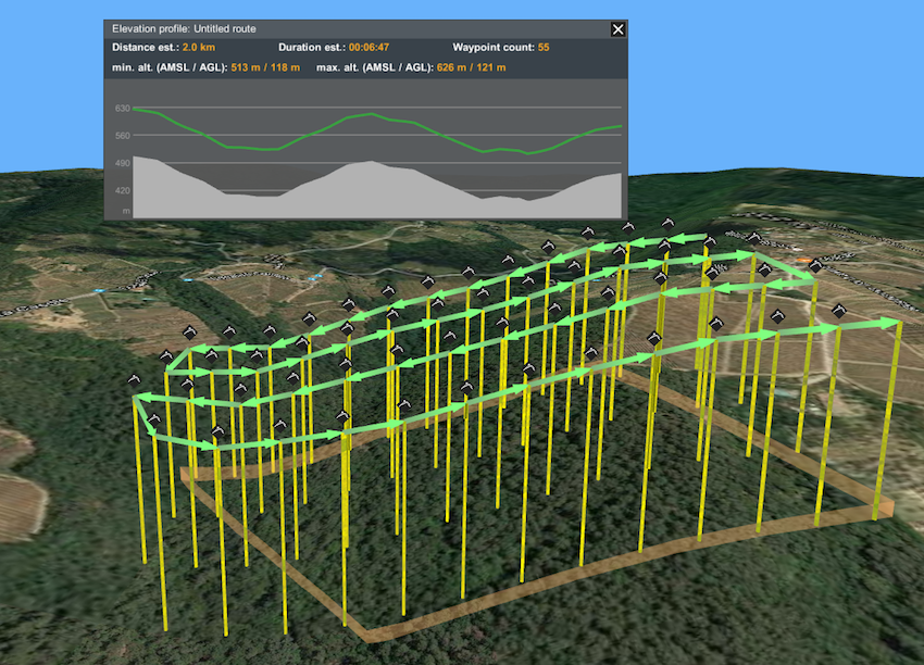
Figure 11: Elevation profile with AGL with additional waypoints
-Speed
In general, if flight speed is increased it will minimise flight time. But high speed in combination with large camera exposure can result in blurred images. In most cases 10m/s is the best choice.
-Camera control method
UgCS supports 3 camera control methods (actions):
- Make a shot (trigger camera) in waypoint,
- Make shot every N seconds,
- Make shot every N meters.
Not all autopilots support all 3 camera control options. For example (quite old) DJI A2 does support all three options, but newer (starting from Phantom 3 and up to M600) cameras support only triggering in waypoints and by time. DJI promised to implement triggering by distance, but it’s not available yet.
Here are some benefits and drawbacks for all three methods:
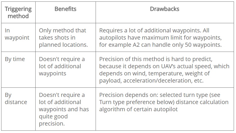
Table 1: Benefits and Drawback for camera triggering methods
In conclusion:
- Trigger in waypoints should be preferred when possible
- Trigger by time should be used only if no other method is possible
- Trigger by distance should be used when triggering in waypoints is not possible to use
To select triggering method in UgCS Photogrammetry tool accordingly, use one of three available icons:
- Set camera mode
- Set camera by time
- Set camera by distance
-Glibal control
Drones, e.g., DJI Phantom 3, Phantom 4, Inspire, M100 or M600 with integrated gimbal, have the option to control camera position as part of an automatic route plan.
It is advisable to set camera to nadir position in the first waypoint, and in horizontal position before landing to prevent lenses from potential damage.
To set camera position, select the waypoint preceding the photogrammetry area and click set camera attitude/zoom (Figure 12) and enter “90” in the “Tilt” field (Figure 13).
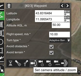
Figure 12: Setting camera attitude
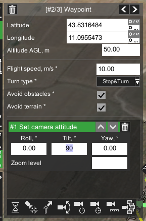
Figure 13: Setting camera position
As described previously, this waypoint should be a Stop&Turn type, otherwise the drone could skip this action.
To set camera to horizontal position, select last waypoint of survey route and click set camera attitude/zoom and enter “0” in the “Tilt” field.
-Turn types
Most autopilots or multirotor drones support different turn types in waypoints. Most popular DJI drones have three turn-types:
- Stop and Turn: drone flies to the fixed point accurately, stays at that fixed point and then flies to next fixed point.
- Bank Turn: the drone would fly with constant speed from one point to another without stopping.
- Adaptive Bank Turn: It is almost the same performance like Bank Turn mode (Figure 13), but the real flight routine will be more accurately than Bank Turn.
It is advisable not to use Bank Turn for photogrammetry missions. Drone interprets Bank Turns as “recommendation destination waypoint”. The drone will fly towards this direction but will almost never pass through the waypoint. Because drone will not pass the waypoint, no action will be executed, meaning the camera will not be triggered, etc.
Adaptive Bank Turn should be used with caution because a drone can miss waypoints and, again, no camera triggering will be initiated.
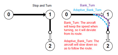
Figure 14: Illustration of typical DJI drone trajectories for Bank Turn and Adaptive Bank Turn types
Sometimes, adaptive bank turn type has to be used in order to have shorter flight time compared to stop and turn. When using adaptive bank turns, it is recommended to use overshot (see below) for the photogrammetry area.
-Overshot
Initially overshot was implemented for fixed wing (airplane) drones in order to have enough space for manoeuvring a U-turn.
Overshot can be set in photogrammetry tool to add an extra segment to both ends of each survey line.
Figure 15: Adding 40m overshot to both ends of each survey line
In the example (Figure 15) can be seen that UgCS added 40m additional segments to both ends of each survey line (comparing to Figure 8).
Adding overshot is useful for copter-UAVs in two situations:
- When Adaptive Bank Turns are used (or similar method for non-DJI drones), adding overshot will increase the chance that drone will precisely enter survey line and camera control action will be triggered. UgCS Team recommends to specify overshot that is approximately equal to distance between the parallel survey lines.
- When Stop and Turn type is in use in combination with action to trigger camera in waypoints, there is a possibility that before making the shot, drone will start rotation to next waypoint – it can result in having photos with wrong orientation or blurred. To avoid that, shorter overshot has to be set, for example 5m. Don’t specify too short value (< 3m) because some drones could ignore waypoints, that are too close.
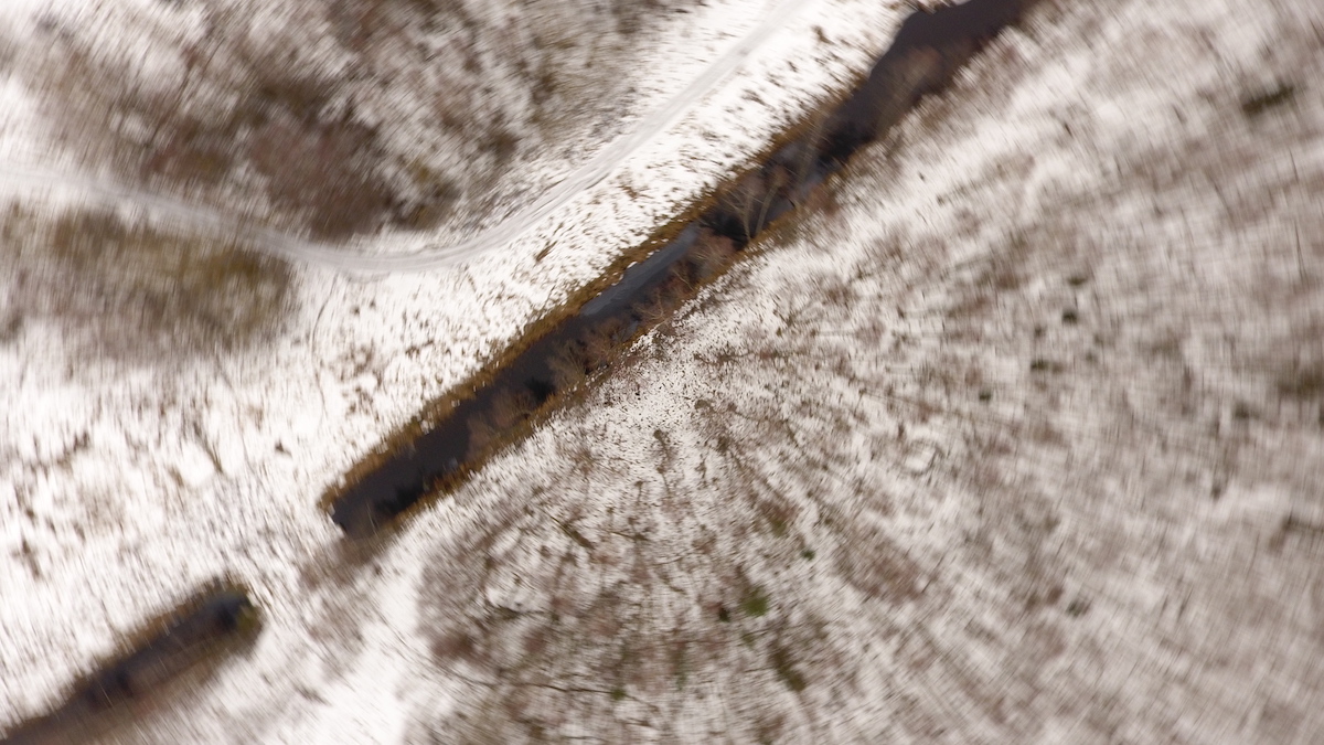
Figure 16: Example of blurred image taken by drone in rotation to next waypoint
-Takeoff point
It is important to check the takeoff area at site before flying any mission! To better explain best practice on how to set takeoff point, first discuss an example of how it should not be done. Supposing that the takeoff point in our example mission (Figure 17) would be from the point marked with the airplane-icon, and drone pilot would upload the route on the ground with set automatic mission for automatic take-off.
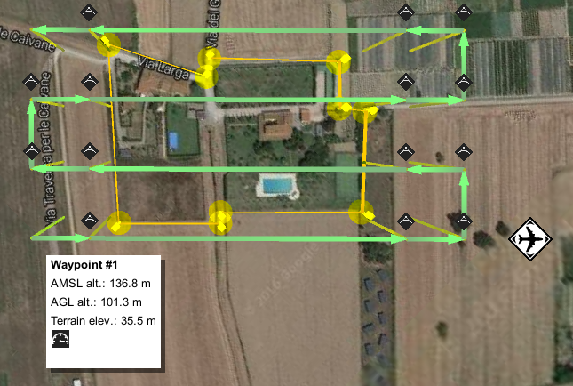
Figure 17: Take-off point example
Most drones in automatic takeoff mode would climb to low altitude about 3-10meters and then fly straight towards the first waypoint. Other drones would fly towards first waypoint straight from ground. Looking closely at the example map (Figure 17), some trees between the takeoff point and the first waypoint can be noticed. In this example, the drone more likely will not reach a safe altitude and will hit the trees.
Not only the surroundings can affect takeoff planning. Drone manufacturers can change drones elevation behavior in drone firmware, therefore after firmware updates it is recommended that you check drones automatic takeoff mode.
Also, a very important consideration is that most small UAVs use relative altitude for mission planing. Altitude counted relatively according to first waypoint is a second reason why an actual takeoff point should be near the first waypoint, and on the same terrain level.
UgCS Team recommends placing the first waypoint as close as possible to actual takeoff point and specifying a safe takeoff altitude (≈30m in most situations will be above any trees, see Figure 18). This is the only method that warrants safe takeoff for any mission. It also protects from any weird drone behaviour and unpredictable firmware updates, etc.
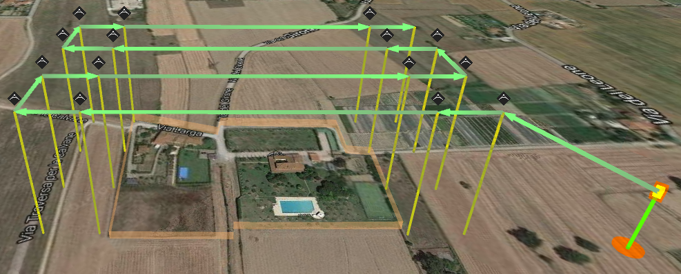
Figure 18: Route with safe take-off
-Entry point to the survey grid
In the previous example, (see Figure 18), it can be noticed, that after adding the takeoff point, the route’s survey grid entry point was changed. This is because if additional waypoint is added subsequently to the photogrammetry area, UgCS will plan to fly the survey grid starting from nearest corner to the previous waypoint.
To change the entry point to survey grid, set additional waypoint close to the desired starting corner (see Figure 19).

Figure 19: Changing survey grid entry point by adding additional waypoint
-Landing point
If no landing point will be added outside the photogrammetry area after the survey mission, the drone will fly and hover in the last waypoint. There are two options for landing:
- Take manual control over the drone and fly to landing point manually,
- Activate the Return Home command in UgCS or from Remote Controller (RC).
In situations when the radio link with the drone is lost, for example if the survey area is large or there are problems with the remote controller, depending on the drone and it’s settings, one of these actions can occur:
- Drone will return to home location automatically if lost radio link with ground station,
- Drone will fly to last waypoint of survey area and hover as long as battery capacity will enable that, then: drone will perform emergency landing, or it will try to fly to home location.
The recommendation is to add an explicit landing points to the route in order to avoid relying on unpredictable drone behavior or settings.
If the drone doesn’t support automatic landing, or the pilot prefers to land manually, place the route’s last waypoint over the planned landing point with an altitude for comfortable manual drone descending and landing above any obstacles in the surrounding area. In general 30m is best choice.
-Action execution
Photogrammetry tool has a magic parameter “Action Execution” with three possible values:
- Every point
- At start
- Forward passes
This parameter defines how and where camera actions specified for photogrammetry tool will be executed.
The most useful option for photogrammetry/survey missions is to set forward passes, the drone will make photos only on survey lines, but will not make excess photos on perpendicular lines.
-Complex survey areas
UgCS enables photogrammetry/survey mission planning for irregular areas, having functionality to combine any number of photogrammetry areas in one route, avoiding splitting the area in separate routes.
For example, if a mission has to be planned for two fields connected in a T-shape, and if these two fields are marked as one photogrammetry area, the whole route will not be optimal, regardless any direction of survey lines.
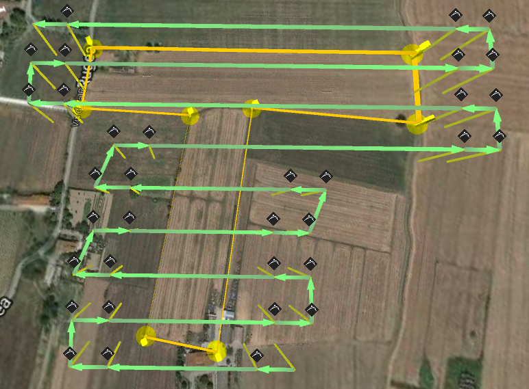
Figure 20: Complex survey area before optimisation
If the survey area is marked as two photogrammetry areas within one route, survey lines for each area can be optimised individually (see Figure 21).
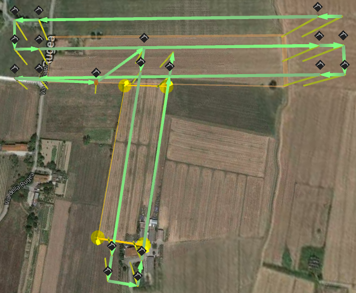
Figure 21: Optimised survey flight passes for each part of a complex photogrammetry area
Step three: deploy ground control points
Ground control points are mandatory if the survey output map has to be precisely aligned to coordinates on Earth.
There are lots of discussions about the necessity of ground control points in cases when a drone is equipped with Real Time Kinematics (RTK) GPS receivers with centimeter-level accuracy. This is useful, but the drone coordinates are not in themselves sufficient because, for precise map aligning, image center coordinates are necessary.
Data processing softwares like Agisoft Photoscan, Dronedeplay, Pix4d, Icarus OneButton and others will produce very accurate maps using geotagged images, but the real precision of the map will not be known without ground control points.
Conclusion: ground control points have to be used to create survey-grade result. For a map with approximate precision, it is sufficient to rely just on RTK GPS and the capabilities of data processing software.
Step four: fly your mission
For carefully planned missions, flying it is the most straightforward step. Mission execution differs according to the type of UAV and equipment used, therefore it will not be described in detail in this article (please refer to equipment’s and UgCS documentation).
Important issues before flying:
- In most countries there are strict regulations for UAV usage. Always comply with the regulations! Usually these rules can be found on web-site of local aviation authority.
- In some countries special permission for any kind of aerial photo/video shooting is needed. Please check local regulations.
- In most cases missions are planned before arriving to flying location (e.g., in office, at home) using satellite imaginary from Google maps, Bing, etc. Before flying always check actual circumstances at the location. There could be a need to adjust take-off/landing points, for example, to avoid tall obstacles (e.g., trees, masts, power lines) in your survey area.
Step five: image geotagging
Image geotagging is optional if ground control points were used, but almost any data processing software will require less time to process geotagged images.
Some of the latest and professional drones with integrated cameras can geotag images automatically during flight. In other cases images can be geotagged in UgCS after flight.
Very important: UgCS uses the telemetry log from drone, that is received via radio channel, to extract the drone’s altitude for any given moment (when pictures were taken). To geotag pictures using UgCS, assure robust telemetry reception during flight.
For detailed information how to geotag images using UgCS refer to UgCS User Manual.
Step six: data processing
For data processing, use third party software or services available on the market.
From UgCS Team experience, the most powerful and flexible software is Agisoft Photoscan (http://www.agisoft.com/), but sometimes too much user input is required to get necessary results. The most uncomplicated solution for users is online service Dronedeploy (https://www.dronedeploy.com/). All other software packages and services will fit somewhere between these two in terms of complexity and power.
Step seven (optional): import created map to UgCS
Should the need arise for the mission to be repeated in the future, UgCS enables importing the GeoTiff file as a map layer and using it for mission planning. More detailed instructions can be found in UgCS User Manual. See the result of an imported map created using UgCS photogrammetry tool imported as GeoTiff file in Figure 22.
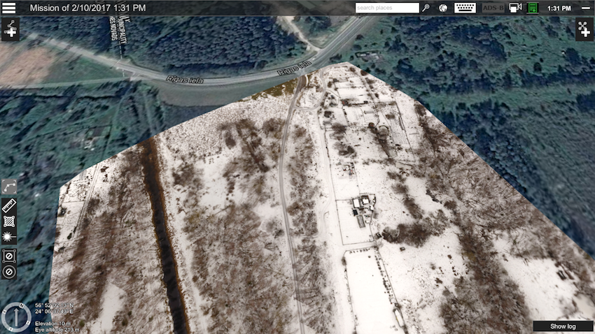
Figure 22: Imported GeoTiff map as layer. The map is output of a Photogrammetry survey mission panned with UgCS
Visit the UgCS homepage
Download this tutorial as a PDF
If you liked this tutorial, you may also enjoy these:
- Programming for robotics: Introduction to ROS
- Python programming your NAO robot
- Robotics, maths, python: A fledgling computer scientist’s guide to inverse kinematics
- Adjust how you learn and quickly pick up robotics programming
- 3-D printing hydraulically-powered robots, no assembly required
See all the latest robotics news on Robohub, or sign up for our weekly newsletter.
tags: c-Aerial, cx-Education-DIY, cx-Exploration-Mining, DIY, Drone, Environment-Agriculture, Flying, how-to, Manipulation, Mapping-Surveillance, Sensing, software, surveying, UAV, video
AUAI is supported by: